| How do I make a Turbo Turbine? |
| Turbo Turbines are very easy to make. First, you need a turbocharger (If you can find one, get one from a petrol engined vehicle as these can stand up to higher RPM's). These can be bought relatively cheaply from your local scrapyard; typical price for a good quality unit is Ł20-30. Before buying, check that there is very little lateral movement of the bearings (about 1 millimetre MAX) and check for physical damage to the compressor and turbine blades. If the turbo does not fit these criteria, PUT IT BACK OR INJURY COULD RESULT!!! Then, take your pride and joy home and clean it up! |
| DISCLAIMER: The Author accepts no responsibility for death or injury as a result of turbo turbine construction. These devices spin at speeds of over 100,000 RPM and will have the same effect as a grenade if they destruct. I also accept no responsibility for partial or complete deafness as a result of improper hearing protection. THESE ENGINES ARE NOT TOYS AND MUST BE TREATED WITH RESPECT!!! |
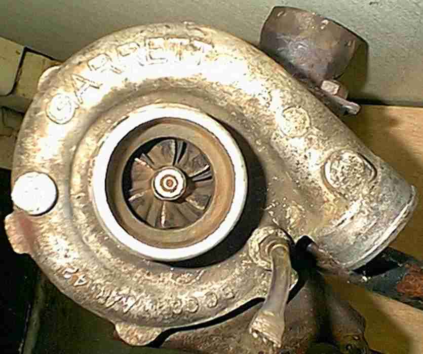 |
| A Typical Turbocharger |
| When the turbocharger is cleaned up, you need to start to think about how to make the air supply and combustion chamber. The first thing to do is construct the combustion chamber. IF IT IS POSSIBLE THE COMBUSTION CHAMBER AND THE FLAME TUBE SHOULD BE CONSTRUCTED FROM STAINLESS STEEL.All this is, is a big METAL pipe with a flange on one end that bolts onto the turbocharger exhaust inlet, and a metal plate on the other end that holds the injector and sparkplug. In most cases it will be likely that an adaptor plate will have to be constructed. For this, use thick plate steel. |
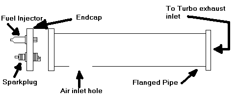 |
| If a flanged pipe is not available, then flanges can be drilled up and welded onto a plain pipe. The next step in combustor construction is the flame tube. This little device is a thin walled metal tube with holes in it. Its purpose is to: 1. Keep the flame from touching the combustor walls, making for cooler running, 2. Contain the flame, and 3. make sure the flame doesnt blow out when the engine is running. The combustor can only be designed by trial and error, but as a rule of thumb the holes should start small at the air intake end, and gradually grow larger. This is so lots of air doesnt enter the flame tube where the fuel is injected as it will blow out the flame. |
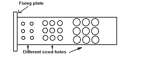 |
| A Typical Flametube |
| So now we have a combustion chamber, a flame tube and an endplate with the sparkplug and adaptor in it. This is how it all goes together: |
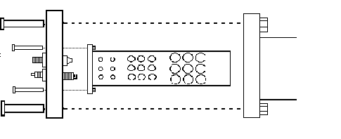 |
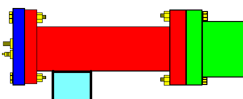
| Exploded Diagram |
 |
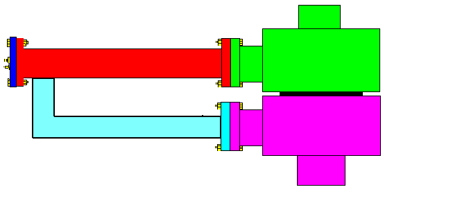
| The almost complete (apart from the air intake) unit is bolted onto the exhaust inlet of the turbocharger. This will give us an indication of how long the air intake 'L' shaped tube has to be. This tube can now be cut. Depending on the size of the combustion chamber, the diameter of the air intake will be about 2-3 inches. Note there is no 'set' size. Now weld the air intake tube onto the combustion chamber, and you will end up with something like the following. The colours are as follows: Red: Combustor Light Blue: Air intake Dark Blue: End plate Yellow: Fittings (Bolts, sparkplug, injector) Green: Exhaust side of Turbocharger Purple: Compressor side of Turbocharger |
 |
| PLEASE BE PATIENT WHILE THIS PAGE LOADS! |
| For a basic engine, that's about it. However, although the engine will run like this, it will not produce very much power. To increase power an exhaust pipe can be added to the turbocharger exhaust output. This is basically just a tube, with a nozzle at the end. This helps to increase exhaust gas velocity, and also creates the opportunity to add an afterburner, which greatly increases power output, but at the expense of crazy fuel consumption (something like 1-1.5 litres PER MINUTE!) For my exhaust pipe system I am planning to use a TKM kart engine exhaust pipe (RRP Ł53.50) as they have a pre made tapered end for a nozzle. |