 |
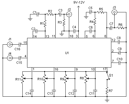
| Parts: Part Total Qty. Description Substitutions C1, C3, C5, C7, C15, C16 6 2.2uf Electrolytic Capacitor C2, C6 2 0.05uF Ceramic Disc Capacitor C4 1 0.22uF Disc Capacitor C8, C10 2 0.015uF Ceramic Disc Capacitor C9 1 100uF Electrolytic Capacitor C11, C12, C13, C14 4 0.1uF Ceramic Disc Capacitor R1, R4 2 10K 1/4W Resistor R2, R5 2 33K 1/4W Resistor R3, R6 2 4.7K 1/4W Resistor R7 1 2.2K 1/4W Resistor R8, R9, R10, R11 4 50K Linear Pot U1 1 TDA1524A Tone Control IC S1 1 SPST Switch J1, J2, J3, J4 4 RCA Jacks Other connectors of your choice MISC 1 Board, Wire, Knobs, 18 Pin Socket Notes: 1. S1 is a contour control. Volume is controlled by R11. Balance is controlled by R10. R9 and R8 control bass and treble, respectivly. 2. J1 is the left input, J4 is the right input. J2 is the left output, J3 is the right output. 3. The circuit is designed to accept line level or mic level inputs. if you are going to be using a stronger signal, a voltage divider will be necessary to cut it down to proper levels. 4. You can, of course, skip J1-J4 if you plan to integrate this circuit into another |
| Bass and Treble Switch |