ΑΡΧΙΚΗ - LINEAR FM 15W - FM 130W - FM 400W - VHF 15W - VHF 30W - UHF 10W
ΕΝΙΣΧΥΤΕΣ ΥΨΗΛΩΝ ΣΥΧΝΟΤΗΤΩΝ
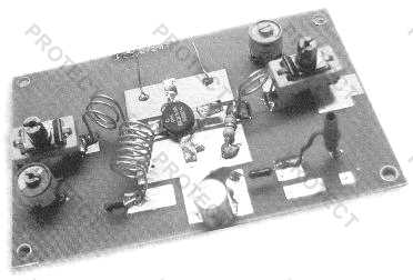
FRB 6 Watt RF Amplifier Kit |
||||||||||||||||||||||||||||||||||||||||||||||||||||||||||||||||||||||||
Assemble by soldering the components to the pads indicated. Keep coil, resistor, and capacitor leads as short as possible. The coils should be 3/16" to 1/4" above the board and separate turns by one wire diameter. Bend leads to form a little mounting foot for soldering to the circuit board. Tuning and power output are affected by the distance between the coil turns, you can make fine adjustments by either spreading or compressing the coil slightly. The area surrounding the pads is ground. C2, C3, C4, C6, C7, C8, C9, C10, L2, and R1 are soldered at one end to ground as well as the shield braid on the coax cables. Bolt Q1 to a small heat sink or the chassis with heat sink thermal compound or gray thermal pad underneath the tab. With an input level of 200-500mw, you should see an output of 5-6 watts. Be sure to have a proper dummy load (50 ohms) or tuned antenna connected to the output, doing otherwise will likely destroy the transistor.
|


LINEAR TV 600mW
Η ενίσχυση του τηλεοπτικού σήματος απαιτεί ένα γραμμικό ενισχυτή, όπου η τάση Vout θα είναι ευθέως ανάλογη της τάσης εισόδου Vin. Ο ενισχυτής λειτουργεί σε τάξη Α ενώ το τρανζίστορ που χρησιμοποιούμε είναι το MRF237. Είναι τύπου NPN και λειτουργεί με τάση 12,5V και είναι σχεδιασμένο για να λειτουργεί σε τηλεπικοινωνιακές συσκευές εως τους 200MHz.
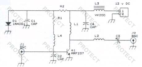
Το MRF237 έχει ισχύ εξόδου 4W στους 175MHz, ελάχιστη απολαβή 12dB και βαθμό απόδοσης 50%. Η σημαντική διαφορά από τα άλλα τρανζίστορ, είναι ότι ο εκπομπός του γειώνεται μέσω του κελύφους του. Μέγιστη τάση συλλέκτη εκπομπού με ανοικτή βάση VCEO=18V και μέγιστο ρεύμα συλλέκτη IC=1A.
Πυκνωτές
C1 - 10 μF/16V (τανταλιου)
C2 - 47 pF (κεραμικoς)
C3 - 2-60 pF (μεταβλητος)
C4 - 10 nF (κεραμικoς)
Υπόλοιπα
L1 - 7 σπειρες σε 7mm διαμετρο
L2 - 4 σπειρες σε 4mm διαμετρο
L3 - VK200
L4 - 10μΗ τσοκ
D1 - 1N4001
T1 - MRF237
Αντιστάσεις
R1 - 100 Ω 1/4W
R2 - 1 KΩ 1/2W
Linear FM ισχύος 30Watt
Kατασκευή: Σούλης Παπαναστασίου
Copyright: Τεχνική Εκλογή


ΥΛΙΚΑ
C1, C2, C3, C4 = 10 – 80pF |
C5 = 10nF |
C6 = 1000pF |
C7 = 100nF |
C8 = 2200mF/35V |
L1 = 1 σπείρα με διάμετρο 10mm, 1mm |
L2 = 7 σπείρες με διάμετρο 10mm, 0,8mm |
L3 = 3 σπείρες με διάμετρο 10mm, 1mm |
TR1 = BLY89 |
RFC = RF τσοκ |