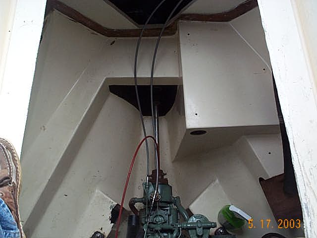
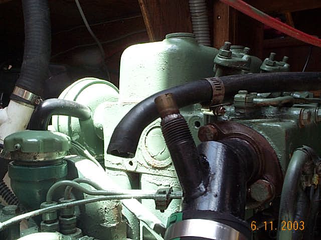
View of the engine room on Synergy. This is what one would see when the cockpit sole (floor) is removed. The old muffler was attached to the engine. Because of the cylindrical shape of the replacement muffler, a custom bracket was required. I selected the starboard side engine-room liner wall because it offered the most space and still provided access to the stuffing box.
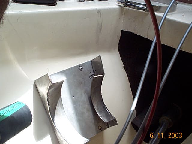
Here is the result of much swearing, cussing and crying: the beginnings of a custom bracket template.
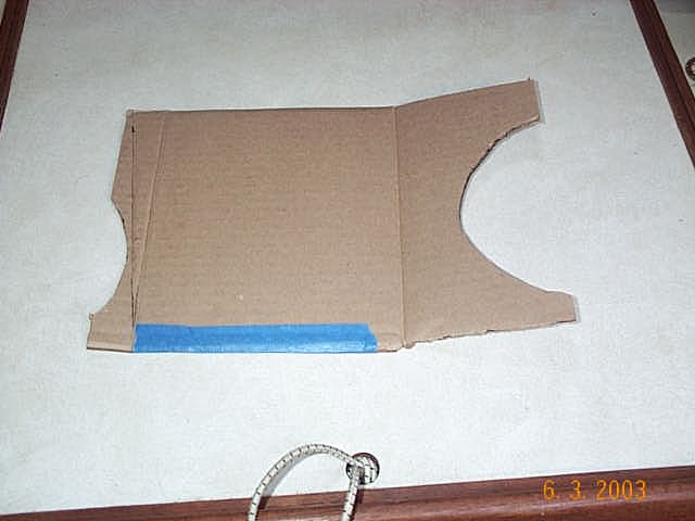
I used cardboard and wire to form the template. Once the final adjustments were made, the template was handed over to a metal shop and a permanent, stainless steel bracket was fashioned.

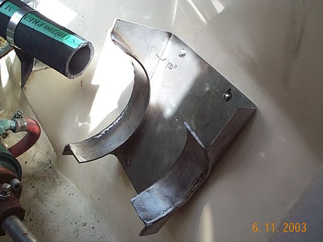
Here the new stainless steel bracket has been mounted with 5200 marine adhesive and four 1" SS screws. Despite their length, the screws never penetrated the hull.

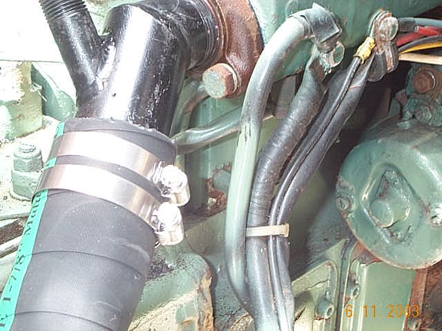
This is a view looking forward with the new exhaust elbow attached to the exhaust manifold. Note the thinner water hose and the 1-7/8" exhaust hose leading to the muffler.

Close-up view of the exhaust hose attachment to the elbow. Always double-clamped!
Close-up view of the elbow with a good view of the water hose joint.
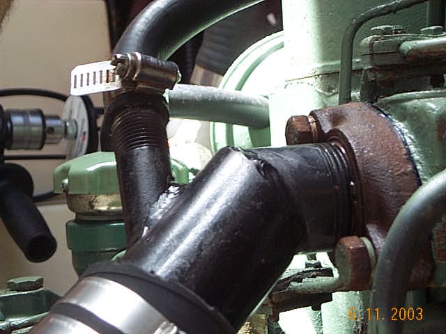
Here I've removed the water hose to expose the nipple on the elbow. The nipple was actually added by a local welder because the factory had shipped the wrong diameter.
Here is a view of the muffler bracket, looking aft. You can see where the curved pieces touching the muffler were widened with two-inch strips to minimize chafe.
Great view of the bracket, looking aft and parallel with the liner wall.

This is one picture that I'm glad I took. It had been a long day by the time I had installed the muffler, and the additional hour that it took to wrangle with the hoses didn't make it any easier. Well, I finished the job and snapped the picture. When I got home and downloaded the photos, I noticed that the muffler was installed backwards (note the large arrow on the sticker)!!! Rest assured, it is now oriented correctly.
