T & C Enterprises
5th wheel jack installation manual
![]()
Contents:
Introduction
Parts list and part identification
Cylinder pre-installation
Screw jack removal
Cylinder installation
Pump installation
Hose connections
Electrical installation
Filling and purging the hydraulics
Use and maintenance
Section 1: Introduction
T & C Enterprises hydraulic jack system is designed to easily install in place of your old screw jacks. The kit comes in two forms, the universal fit and custom fit.
The "Universal fit kit" will fit any 5th wheel but requires some arc welding on the cylinder mounting brackets to "fit" them to your trailer. Any local RV service center or welding shop should have no trouble with these simple wields.
The "Custom fit kit" is shipped with pre wielded cylinder brackets made to fit into your 5th wheel's old screw jack brackets. Custom fit kits can be ordered at no additional charge for any 5th wheel. You must provide the make and model of your 5th wheel along with measurements between the clamp straps on your screw jacks and the distance from the lower strap to the bottom of the trailer.
The pump can easily be mounted next to the cylinder in the forward storage area.
Electrical connections run from the trailer battery to the motor and to an up/down switch mounted to work as your old screw jacks control switch.
Installation of the jack system requires NO modifications to your trailer, NO welding, drilling or modifications.
Due to the nature of hydraulics, the cylinders are self leveling, The cylinders will balance the pressure from one side to the other to lift with the same pressure on the left and right side even if the blocking height is a foot or more different!
Section 2:Parts list and part identification
Part No. Quan Description
--1-- Hydraulic pump and reservoir
--4-- 3/8 to ¼ reducer fitting
--3-- ¼ short pipe
--2-- swivel T with male and one with female pipe connection
--2-- ¼ swivel
--1-- one way flow restricter
--4-- wire terminals
--1-- control switch with leads
--4-- 24" hydraulic hose
--2-- 72" hydraulic hose
--2-- hydraulic cylinders with mounting brackets
--4-- mounting bracket weld on lugs (pre welded on custom cylinders)
--4-- jack mounting straps (may not be required)


![]()
Section 3:Cylinder pre-installation
If you purchased the custom fitted cylinders SKIP this section.
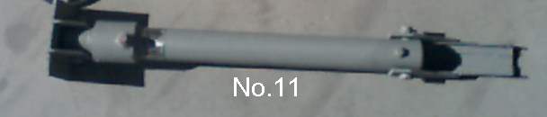
To mount your cylinders you must weld the two ¼" thick steel strap "Lugs" (Part 12) onto each of the cylinders (Part 11). To locate these "Lugs" measure the distance from the top of the upper jack mounting strap on your trailer to the bottom of the trailer.
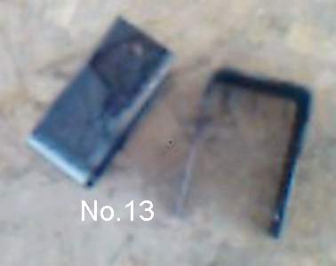
This strap you are looking for should be welded to the frame of your trailer and should look like the replacement strap (Part 13). If your trailer does not have the same type of strap you may need to have the 4 straps (Part 13) provided in the kit welded into your trailer.
Once you have this distance measure up the cylinder mounting bracket the same distance and mark the top of the upper "Lug". The lower "Lug" is located by measuring up from the bottom of the trailer to the bottom of the lower jack mounting strap on your trailer. Measure up on the cylinder mounting bracket and mark the bottom of the lower "Lug"
Weld the 2 "Lugs" on the flat side (opposite the cylinder) of the cylinder bracket.
If all this sounds complicated, it is not, the location of the "Lugs" is not critical, they are there to transfer the load from the cylinder bracket to your trailer's strap clamps and to keep the entire cylinder from moving up or down.
The range of motion of the jacks may set by where the "Lugs" are welded, keep this in mind when preparing the cylinders and the "Lug" locations.
Your local RV dealer has installed many of the older screw jacks and this step of the lug instillation is JUST the same as on the screws.
Section 4:Screw jack removal
Removal of your old screw jacks varies depending on your trailer but basically requires the removal of the 4 bolts holding the strap clamps around the jack screw tubes, disconnecting the wiring (if electric) and disconnecting the cross connect drive shaft from the gear boxes.
With the fifth wheel supported and blocked crank the screws up and disconnect the wires, cross shaft couplers and strap bolts. Be careful the jacks don't fall, blocking should be placed under the raised jack foot to keep it from falling.
Once the jacks are loose, swing the foot toward the center of the trailer and pull it out the opposite side.
Section 5:Cylinder installation
With the fifth wheel supported and blocked it should be simple to set the cylinders into the strap clamps on the trailer. Be sure the hoses can be connected. Install the 4 bolts in the strap clamps, do not bend the straps by over tightening the bolts.
For
all fittings you will need a roll of teflon thread seal tape or a
tube of loctite hydraulic thread sealer. On the cylinder nearest the
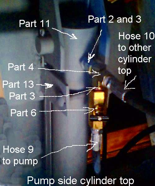
pump (part 1) the top fitting will have the following:
Part 2 - part 3 - part 4(with male pipe in center of T)
in the center of part 4 - part 6, be sure the arrow on the side of part 6 is pointing away from the "T" (Part 4) if you reverse this the jacks will lift slowly and drop quickly.
On the bottom of this cylinder (Part 11) install the following:
Part 2 - part 3 - part 4(with female pipe connection in center of T)
On the other cylinder install Part 2 in the upper and lower connections
Section 6:Pump installation
Remove the plastic caps and install the swivels (part 5) in the ports of the pump, don't forget the thread seal.
To mount the pump and reservoir, locate a solid flat area on the left or right side of the front storage locker be sure to leave room for hoses and wire connections. The pump must be within 24" of the top of one of the cylinders! Test the position by holding one of the 24" hoses (Part 9) from the pump connections to the upper and lower cylinder connections. The kit includes 2 extra 24" hoses to allow locating the pump farther than a single 24". If you need to use these hoses simply buy 2, ¼ pipe connectors to add the extra 24" If you can't find a good location close to the cylinders you can get longer ¼" hoses locally. Be sure there is room above the pump and reservoir to allow connection of the hoses and FILLING the reservoir.
Section 7:Hose connections
 Be
sure to use thread sealer on the hoses.
Be
sure to use thread sealer on the hoses.
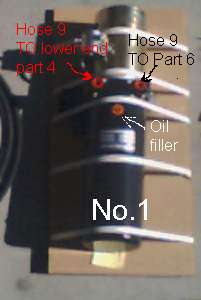
Connect the first 24" hose (Part 9) from the top of the cylinder nearest the pump at part 6 to the pump at the port to the right of the oil filler plug when the filler is nearest you and the hose connections are away from you.(see photo--->) Tighten the swivel "T" connection after the cylinder connection.
Second 24" hose (Part 9) from the bottom of the nearest cylinder at the center of the "T" (part 4) to the pump left of the oil filler plug when the filler is nearest you and the hose connections are away from you.
First 72" hose connects the top of each cylinder. Start by connecting the hose to the cylinder away from the pump. Then to the swivel "T" part 4 at the top of the nearest.
Second 72" hose connecting the bottom of each cylinder. Start by connecting the hose to the cylinder away from the pump. Then to the swivel "T" part 4 at the bottom of the nearest.
Section 8:Electrical installation
Measure from your battery to the Pump (part 1) and cut the heavy copper wire. Strip back the ends of the wire ½ inch. Clamp the 4 wire terminals, Part 7, on the ends of the wire. Connect the - (NEG) battery terminal to one of the bolts on the pump base.
Connect one end of the heavy copper wire terminals and the black wire with the large terminal ring of the control switch assembly (part 8) to the large motor solenoid post on the pump. Connect the white (of part 8) to the smaller solenoid post and the green wire over to the reversing valve connector post on the side of the pump.
Mount to the switch in an accessible location. And finally connect the large wire from the pump's solenoid to the +terminal of your battery.
Section 9:Filling and purging the hydraulics
Getting all the air out of the cylinders is important!!! With the trailer blocked and on the hitch and no load on the jacks and an unrestricted full length travel add oil and purge the air from the system. If you can't jack the 5th wheel high enough to allow full travel of the cylinders you can remove the lower strap clamp bolts and swing the feet of the cylinders in to provide more room for travel. Use 10 weight hydraulic oil or ATF (automatic transmission fluid). A funnel may come in handy and keep from spilling oil.
Remove the oil filler plug, fill the reservoir to within a ½" from the top. Now press the switch up or down, oil will be pumped into the cylinder and air will forced to return. This will lower the oil level, continue running the pump until you can't see the oil level. Add oil and repeat this process. It is best to fill the reservoir when the jacks are in the up position. If you fill the reservoir full with the cylinders down you may have a problem of overflowing the reservoir as the cylinders come up. The cylinders hold more oil in the down position than when they are in the up position.
DO NOT run the pump with the filler plug installed until you get the air out.
If the cylinders don't move smoothly you have AIR in the cylinders and need to keep running them up and down from top limit to bottom limit. This may take a dozen or more strokes. Of course if the reservoir runs low while running the pump you will just get more air in the system.
As you run the pump you may get large and small air bubbles that may cause the reservoir to overflow, don't worry. The more of a hurry you get in the more oil you are likely to spill, TAKE YOUR TIME.
It is normal for one cylinder to move before the other.
Section 10: Use and maintenance
Pre-flight check, as the airplane pilots say, simply amounts to charging the battery, hitching the 5th wheel and raising the cylinders to the fully retracted position. Now remove the oil filler from the top of the pump and check the oil level. With the cylinders fully retracted the reservoir should be FULL. Top off the pump reservoir with 10 weight hydraulic oil or automatic transmission fluid.
Due to the nature of hydraulics, the cylinders are self leveling, The cylinders will balance the pressure from one side to the other to lift with the same pressure on the left and right side even if the blocking height is a foot or more different! If your trailer is quite a bit off balance to the left or right side this self leveling function will tend to lift the lighter side higher than the heavy one. Your rear jacks and axles will handle any normal imbalance. Any 5th wheel mis-loaded enough to cause uneven jacking will NOT work well going down the road!
Adjustments:
When lowering the 5th wheel onto the hitch or stand the down speed can be adjusted by turning the screw on the flow restricter valve (part 6). If the 5th wheel drops too quickly give the valve a turn in (clockwise) and try it again. If it drops too slowly turn the valve out (counter clockwise).
END