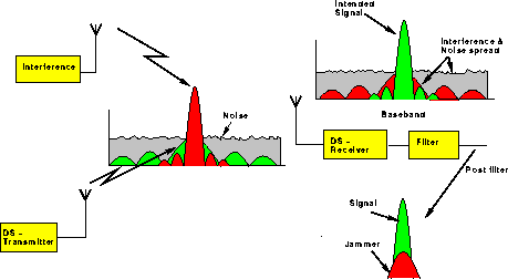
The DSSS process is performed by combining an RF carrier with a higher data rate bit sequence called a pseudo-noise (PN) digital signal. The PN code, which many refer to as a chipping code or processing gain, may contain sequences as short as 11 bits or as long as [2^(89) - 1], have been employed for this purpose, at code rates from under a bit per second to several hundred megabits per second. A high processing gain increases the signal's resistance to interference. The minimum linear processing gain that the FCC allows is 10, and most commercial products operate under 20. The IEEE 802.11 Working Group has set their minimum processing gain requirements at 11.

| A Spectrum Analyzer Photo of a Direct Sequence (DS) Spread Spectrum signal. |
The process begins when the chipping code is modulated onto the information signal. Then, a doubly balanced mixer is used to multiply the RF carrier and chipping code modulated information signal. This process causes the RF signal to be replaced with a very wide bandwidth signal with the spectral equivalent of a noise signal. The demodulation process is then simply the mixing/multiplying of the same chipping code modulated carrier with the incoming RF signal. The output is a signal that is a maximum when the two signals exactly equal one another or are "correlated." The correlated signal is then filtered and sent to a 2-phase digital demodulator.
The result of modulating an RF carrier with such a code sequence is to produce a signal centered at the carrier frequency, with a spectral content of an SS signal with a (sin x/x)2 form. The bandwidth in DSSS systems is often taken as the null-to-null bandwidth of the main lobe of the power spectral density plot, which is twice the clock rate of the modulating code. The side lobes have a null to null bandwidth equal to the code's clock rate. Therefore, the bandwidth of a DSSS system is a direct function of the modulating code. The signals generated with this technique appear as noise in the frequency domain. The wide bandwidth provided by the chipping code allows the signal power to drop below the noise threshold without loss of information. It should be noted that the power contained in the main lobe comprises 90 percent of the total power. This allows a narrower RF bandwidth to accommodate the received signal with the effect of rounding the received pulses in the time domain.
| DS-concept, before and after despreading. |
 |
One feature of DSSS is that 4-phase digital modulation may be used to increase the data rate. This is an increase of a factor of two bits per symbol of transmitted information over 2-phase digital modulation and causes an equivalent reduction in the available process gain. The process gain is reduced because for a given chip rate, the bandwidth (which sets the process gain) is halved due to the two-fold increase in information transfer. The result is that systems in a spectrally quiet environment benefit from the possible increase in data transfer rate
Frequency Hopped Spread Spectrum (FHSS)
Frequency hopping relies on frequency diversity to combat interference. This is accomplished by multiple frequency, code selected, FSK. Basically, the incoming digital stream is shifted in frequency by an amount determined by a code that spreads the signal power over a wide bandwidth. In comparison to binary FSK, which has only two possible frequencies, FHSS may have 2*10^20 or more.

| A Spectrum Analyzer Photo of a Frequency Hop (FH) Spread Spectrum signal. |
The FHSS transmitter is a pseudo-noise PN (or hopping) code controlled frequency synthesizer. The instantaneous frequency output of the transmitter jumps from one value to another based on the pseudo-random input from the code generator. Varying the instantaneous frequency results in an output spectrum that is effectively spread over the range of frequencies generated. To properly receive the signal, the receiver must either be sent the same hopping code or know it before the transmission begins so that it and listen to the incoming signal at the right time and correct frequency.
The bandwidth of the system is simply w times the number of frequency slots available, where w is the bandwidth of each hop channel. Hence, the process gain is directly dependent on the number of available frequency choices for a given information rate.
| Illustration of the frequency hopping concept. |
 |
Another important factor in FHSS systems is the rate at which the hops occur. The minimum time required to change frequencies is dependent on the information bit rate, the amount of redundancy used, and the distance to the nearest interference source.
It is possible to have operating radios use spread spectrum within the same frequency band and not interfere, assuming they each use a different hopping pattern. While one radio is transmitting at one particular frequency, the other radio is using a different frequency. A set of hopping codes that never use the same frequencies at the same time are considered orthogonal
A Side-By-Side Comparison
| Direct Sequence | Frequency Hopping |
|
|