ALL WHEEL DRIVE 6000 INFORMATION


AWD Pontiac 6000 STE Specifications (1988 – 1989), 1990 SE Similar
Powertrain
Engine: 60° V-6 (VIN T) (RPO LHO)
Displacement: 3.1L / 192 cu. in.
Power: 135 hp @ 4800 RPM
Torque: 180 lb. ft @ 3600 RPM
Compression Ratio: 8.8:1
Bore x Stroke: 89mm x 84mm / 3.503" x 3.3122"
Firing Order: 1-2-3-4-5-6 (Same as 2.8L)
Spark Plug Gap: 1.14mm / .045”
Drivetrain
Transmission: THM-125C 3 Speed Automatic Transaxle
Torque Distribution: 60% Front / 40% Rear
Front Planetary Differential Ratio: 2.84:1
Helical Transfer Case Gear Set Ratio: 0.74:1
Spiral Bevel Gear Ratio: 1.12:1
Rear Differential Ratio: 3.42:1
Brakes
Front Brakes: Hydraulic Antilock Disk 260mm Rotor
Rear Brakes: Hydraulic Antilock Disk 265mm Rotor
Capacities
Crankcase: 3.78L / 4 Quarts (more if filter is changed)
Fuel Tank: 62L / 16 US Gallons
Engine Cooling System: 11.9L / 12.6 Quarts
Transaxle Drain & Refill: 3.78L / 4 Quarts
Air Conditioner: (R-12 Refrigerant) 1.25 kg / 2.75 lbs
Rear Axle: (SAE 80W-90 GL-5) 1.8L / 1.9 Quarts
A special thank you goes out to the many thousands of employees of the Pontiac Motor Division of General Motors Corporation and its suppliers who designed and built one of the most rare and unique vehicles of the 1980's. The vehicle's driveline is a real tribute to excellence in mechanical engineering and high-quality fabrication. The oddities in its assembly are certainly a tribute to the men and women who actually put the car together on the assembly lines. As an aside, no thanks goes out to whoever is responsible for the cheap steel in the body and components, or for placing the fuel filter immediately in front of the left rear wheelhouse.
STE AWD TRANSFER CASE

Figure 1. Transfer case (orange) is bolted on to a modified THM-125C 3-speed automatic transmission (blue). This is serviced as a complete unit (including the transmission), so there are no individual parts for the transfer case available from the dealer. The seals for the propeller shaft flange and the drive axles can be purchased from an aftermarket parts dealer. Although parts are unavailable, schematics for the inner-workings of the unit are. These are shown in the figures below.

Figure 2. Sections of the transfer case.

Figure 3. Powerflow to front wheels.

Figure 4. Powerflow to the rear wheels.

Figure 5. Transfer case locking mechanism. The locking mechanism forces the front axle to rotate at the same rate as the rear axle. This does not mean that all four wheels will rotate when all the wheels are on a low-friction surface such as ice. It means that AT LEAST one of the front wheels and at least one of the rear wheels will turn in a low friction condition. This also implies that the vehicle (in theory) could spin only one tire when the case is not locked in a low friction condition. You should never lock the transfer case in normal driving conditions as you may put yourself in a very dangerous situation (see no parts available above). Also be warned that locking the transfer case can make it very difficult to steer the vehicle. Thus locking the transfer case while driving could cause a loss of vehicle control. While it is debatable whether the transfer case will actually lock at normal driving speeds, in theory it is possible and will result in a dangerous condition as the transfer case will not unlock until pressure from the gear mesh is reduced to the point where the mechanism can unlock itself. In addition, you've probably noticed that the anti-lock (ABS) function of the brakes is disabled when the transfer case is locked. Locking the transfer case, of course, should only be used according to the instructions in the owner's manual or on the back-side of the driver's sun visor. The good news is that your vehicle will almost never get stuck if you stay on the roads.
PROPELLER SHAFT
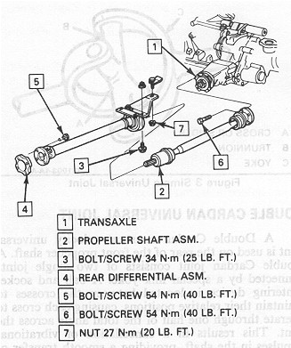
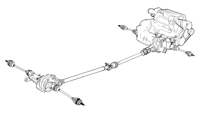
Figure 1. Propeller Shaft Assembly.
One of the components that may need periodic servicing is the propeller shaft assembly. There are a few things one should realize before servicing the propeller shaft assembly. The first is NO service parts are available from the dealer. If you have a major problem with the shaft, you will have to replace the entire assembly (see part numbers in the table below). The second is that the propeller shaft assembly will make your rides in the car miserable from vibrations if it is out-of-balance or has constant velocity joints that are failing. Therefore, be careful when working on or around the propeller shaft as the consequences are very severe if a mistake is made.
First, a disclaimer needs to be made. The picture above is for a very few, if any, production shafts in existence. The only difference is that most shafts have a double-cardan (two U-joint assembly) where the arrow labeled 2 is pointing. It should be noted that this double-cardan joint also has a centering ball that needs to be greased periodically with a greasing needle. If you don't know what I'm talking about, talk with a mechanic or do a little research. Greasing this centering ball will increase the life of the double-cardan joint assembly.
When servicing the shaft, you will find that front end that connects to the transfer case has a strange looking "can" with what looks like a small black toilet plunger diaphragm surrounding the shaft. This is the cross-groove constant velocity joint. You must inspect this rubber seal to ensure that there are no cracks. If this joint should fail, you can obtain a replacement from Rockford Driveline. Be aware that this replacement is not an exact one and is not what the OEM engineers had in mind for a seal. Another alternative is locating an AWD Astro/Safari van in a junkyard and buying the line-shaft that has a similar cross-groove joint. I'm not sure if this will work for sure, but I've heard talk that it may be possible. There are few alternatives when the cross-groove joint fails and most solutions are expensive, so be especially careful with the cross-groove joint and its seal.
The double-cardan joint has a few serviceable items. As mentioned, the centering ball need to be greased periodically. Also the U-joints in the assembly may need to be greased, if they are the greaseable ones with zerks. The U-joints themselves can be purchased from an aftermarket source. Bring the joint with you to the store as they are almost guaranteed not to have a listing for the AWD 6000 in their application books, if they do, it's probably the wrong joint size. All this is true as well for the single cardan joint in the rear of the shaft, near the differential.
As seen in Figure 1, the propeller shaft is a two piece assembly. Where the two pieces come together, there is a center bearing. This center bearing is mounted in rubber and attached to the car via a circular steel-holder and a vibration isolator bracket. As of the time which this was written, I have not been able to find a replacement center bearing with the required 32mm I.D. Therefore, treat this bearing with extreme care, and do not assume that you will be able to replace it until you have a replacement part in your possession. The vibration isolator that the center bearing is attached to is available (maybe) from the dealer and is listed in the table below.
Also keep in mind that each piece of the shaft is balanced at the factory. Therefore, if a balance weight falls off, you may attempt to balance the shaft using the procedure outlined in the factory service manual, or it is recommended that you send the shaft out for rebalancing. In addition, always mark the position of every piece of the shaft you remove, relative to the piece it attaches to, to ensure that the parts get reassembled to their original orientations. The OEM engineers allowed the support bracket, above the center bearing, to be adjustable to align the shaft with the driveline components. Therefore, mark the support relative to the car before removing it for any reason.
Propeller Shaft 26013594 2,000
Front Flange Bolt M10x1.5x25 11504596 0.68
Rear Flange Bolt M8x1.25x22.79 1261592 0.50
Support Bracket (No bearing) 10091900 14.00
This information and pics curtousy of This website (author unknown)
BACK
This website is in no way affiliated with General Motors Corp, any of its subsidairys, or any other commercial companys listed within. It is a non profit website for fans of pontiac 6000's. All GM logos, vehicles, and parts names are registered trademarks of General Motors corp.


