
This is a short article intended to show how to hook up common simple pieces of hardware to a uC. Other more complex/advanced pieces of hardware will be covered in other articles.
Note: Any referenced to power will be of the uC's system power supply and not of the input power supply. This means Vcc is the uC system voltage and not the input voltage (i.e. nine volts).
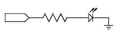
Connecting a LED to the uC is not that hard. Make sure that you observe the current ratings of your uC and LED. Do not get comfortable and try to take advantage of the limited current supplying ability of the output to release you of the need for a current limiting resistor. You are asking for trouble. Use an appropriate current limiting resistor.
Note: Some uC outputs cannot sink/source the same amount of current. Some outputs may not even be able to both sink and source current. All the more reason to check your data sheet.
To source current arrange the LED with the cathode to ground (Figure 1). The LED will turn on when the output is high. To sink current wire the cathode to the uC (Figure 2). The LED will turn on when the output is low.
|
|
|
| Figure 1 | Figure 2 |
If your uC can handle sinking/sourcing current then you can play with bi-colour LEDs. Some bi-colour LEDs have only two legs with each diode conducting in the opposite direction (Figure 3). To turn on one colour set the uC pins according. For the other colour reverse the pin states. To turn off the LED set both pins either on or off. You can turn on both colours by alternating the pin states very quickly.

Other bi-colour LEDs have three legs with each of the diodes cathodes joined together making the third leg. If you are going to use only one colour at a time then you can put a resistor in series with the cathode to ground (Figure 4). If you are going to use both colours at the same time put a current limiting resistor in series with each LED's anode (Figure 5). This will make sure that as a LED is switched it does not affect the brightness of the other LED.
 |
 |
| Figure 4 | Figure 5 |
Turning the different colours on and off is a matter of controlling the uC's outputs. You can have both colours easily by switching both outputs on. These LEDs also tend to be a good option for uC with outputs that cannot sink current thereby it cannot use the two legged bi-colour LED.
Different arrangements of switches can be hooked up to a uC. The matter of if the switch is a pushbutton, lever, rotary, toggle, momentary, rocker, slide, membrane, tactile, reed, etc. is largely irrelevant to the uC as all the uC cares about is high and low logic states. Any operational differences can be handled in the software. Right now we are concerned with how to connect a basic switch to our uC.
A switch arrangement that should work with just about every uC is a SPDT switch with each end connected to power supply positive and ground respectively (Figure 6). An alternative version using a SPST switch can be made by connecting the switch to ground and putting a pull-up resistor on the I/O pin input so when the switch is open the pin is brought high by the pull-up resistor (Figure 7). When the switch is closed it will ground the input creating a logic low state.
 |
 |
| Figure 6 | Figure 7 |
Note: Watch the resistor value you select for your pull-up. If you choose a resistor value that is too high you may not be able to get the input past the uC's high logic voltage threshold when the switch is open. If you use too low of a value you will pull alot of needless current through the resistor when the switch is closed. Typical pull-up values range from 10K-100K.
If your uC has a internal pull-up resistor for the input you can simplify the circuit even more just by using a SPST switch connected to ground (Figure 8) and enabling the internal pull-up resistor. When the switch is open the internal pull-up will bring the input high. When closed the input will be grounded. This greatly reduces the amount external parts needed for the system.

If you have read the previous article "Follow Debouncing Ball" the issues of switch bounce still apply but with uCs the problem of switch debouncing can be solved in the software. This topic is complex enough that it is really deserving of it's own discussion so I won't cover it here. Just be aware of the issue.
Many uC have an internal clock to keep the part count down and the circuit simple. For most uses this internal clock will serve the needs just fine. The internal clock is sensitive to voltage, temperature, and other factors which can change the speed of the clock. If anything being done is time sensitive then the internal clock cannot be trusted. Some uC do not have a internal clock to begin with. In these cases an external clock source is needed.
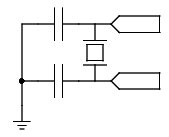
A common external clock source is a crystal. Crystals are not hard to use as most uC has almost all the facilities to use a crystal on board. Usually all is needed is the crystal and a couple of decoupling capacitors (Figure 9) along with any necessary uC internal configuration changes which are usually done through the uC's programmer.
That is it for our quick tour of using basic hardware.
Your Tone God,
Andrew