Figure 1

Figure 2
Welcome to the first of what may hopefully become a continuing series of articles on using microcontrollers in audio electronics. Lets get to work.
More then half of the computers sold every year are microcontrollers. Where are all these microcontrollers ? As you read this you probably have already made use of several devices that have microcontrollers in them. Your alarm clock, watch, cell phone, pager, oven, toaster, fridge, furnace, air conditioner, phone/answering machine, television, television remote, vehicle, vehicle keyless entry, VCR, DVD player, CD player/stereo, portable digital music player, printer, mouse, keyboard, hard drive, USB devices, even that annoying singing birthday card have microcontrollers in them.
Lets talk about computers in general first. A computer in it's simplest form is a device that takes input data, does something with the data, then outputs the data. That is pretty much it. A computer can wait until you clicked on the link to this article with your mouse, do a bunch of stuff to get the article, then output it on the screen or a computer can wait till you flip a switch, figure out what to do with the switch state, then turn something on/off. All that is really different is the complexity of the computer's function.
Computers can be generally broken down into two groups. General purpose computers and specific purpose computers. Normally when the term "computer" is used most think of a desktop computer just like that box humming away while you read this but you can not only browse this article but also use it for email, play music and movies, games, word processor, spreadsheets, etc. That one computer can do alot of different things without having to do too much to it.
Specific use computers like microcontrollers (uC), also referred to as embedded computers as they usually integrated into a system to provide some type of control, are very task specific. Typically uC are used when performing various specific functions have become too difficult or costly to do with discreet electronics. Unlike the desktop computer which can do alot of different tasks you can't, and probably wouldn't want to, use your toaster's computer to also control your car's ignition. Since uC specialize in very specific tasks they do it very well and thus need far fewer resources for the task at hand. That is what makes them so useful compared to a general purpose computer.
So if uC are task specific how come they can be used in so many different things ? As with your desktop computer what can and cannot do depends on the hardware and software you use. The same applies for uC. There are some differences though.
To make your desktop computer function a bunch of different hardware parts need to be connected together like the CPU, memory, BIOS, motherboard, etc. as well as software like the kernel, operating system, device drivers. and applications. Most uC have all the hardware and software needed to function in a single part. This reduces the size and complexity of the uC greatly thus allowing the designer to spend more time working on the system the uC will be apart of and not on the uC itself.
On the hardware side most uC systems can be as simple as a single IC or be very complex with lots of external devices attached to provide the necessary functionality. With a desktop computer you can add or remove devices to/from the system along with the necessary software to change the computer's functionality. Typically with uC systems the hardware is predefined at design time so you cannot change the hardware of the system.
On the software side when you get a uC it's functionality is not defined until you program the software into it. With a desktop computer you can load different software to add or change functionality. With a production uC system typically you load the software once and the user cannot change it afterwards to add or change functionality.
So what can we effect folk do with a uC ? As the name states these are microcontrollers so their main function is to control stuff. They can control things like lights, relays, analog multiplexers, etc. They are microprocessors so almost any place that you have seen digital logic used you can use a uC in it's place such as for decision making or low level data manipulation. Since uC have the ability to access memory you can have them store information like presets or banks. There are a whole host of other functions they can do as well.
What you cannot do with a uC is process anything with high volumes of data or math like analog audio signals. That is what Digital Signal Processing (DSP) is for which is a whole other topic. This is why there will be no uC time based effects or anything of that kin.
If this were a complete introduction right now I would start talking about architecture, stacks, buses, memory, and other technical stuff. I'm not going to. There are plenty of resources online, and of course the datasheet, that will teach you these details better then I can. If we were going to be programming in some other language we may have needed to learn those details right now to get start but instead we are to let the compiler take care of these details for us. You still should learn these details eventually.
Go and download AVR Studio and any of it's service packs, patches, and any need plugins from the following sites:
Atmel AVR Studio
Atmel's Beta Software (Patches, service packs, and plugins)
Go grab a copy of WinAVR from the following site:
I recommend installing WinAVR first. WinAVR comes with a collection of tools to program for the AVR with C. One of the tools it comes with is called "Programmers Notepad". This is a simple editor that you can use to write software and run the compiler from. Recently AVR Studio gained a GCC plugin which adds an integrated editor for GCC which I recommend to save you time switching between programs and playing with other details. If you don't like the editor that AVR Studio provides you can install Programmers Notepad. There are other editors that can be used with GCC if you don't like any of these options.
Install WinAVR as with any normal windows software package. Accept the standard software paths. If you plan on using AVR Studio or some other program as your editor you can deselect "Programmers Notepad" to save space.
Next install AVR Studio. After AVR Studio is installed install any service packs and patches. The AVR-GCC plugin should find your WinAVR installation automatically.
Tip: If you are not sure about getting into uC you can try your hand at coding and simulating the processor with no cost. Then you can decided if you want to spend on the money on the hardware.
The STK500 User Guide that comes with the kit has a pretty good "Getting Started" (Section 2) so I'm not going to repeat. Hook up your STK500 as per the instructions. The STK500 usually comes with a processor pre-installed with some simple programs to let you test and play around with the LEDs and buttons. Once everything is working and your finished playing turn off the STK500, disconnect any header cables, and carefully pop out the processor that came with board.
Fire up AVR Studio and attempt to connect to the STK500 to make sure everything is hooked up correctly. This is covered in "Using AVR Studio" (Section 5) of the STK500 User Guide or you can use AVR Studio's help function.
Note: If your STK500 did not come from Atmel recently it may need a firmware upgrade. When connecting to the STK500 AVR Studio will check to see if you have the newest firmware version installed. If you do not it will give a message and instructions on how to upgrade the firmware. Follow them. Also read the read the Miscellaneous portion of the Hardware Description section (Section 3.10) regarding the PROGRAM Push Button (Section 3.10.2). Upgrading the firmware should not take more then a couple of minutes to do.
Wire up the STK500 to program a Tiny13 in ISP mode. How do you do it ? I'm not going to tell you. I'm sure your smart enough to read the AVR Studio manual/help section.
Note: The manual that comes with your STK500 will probably be out of date. Atmel distributes the latest information with it's AVR Studio releases so read the manual/help file that comes with AVR Studio to absolutely sure.
Make sure a Tiny13 is installed in the correct socket. Connect with the STK500, select the proper processor under "device" (ATtiny13), select "ISP" under "programming mode", then click on something like the "fuses" tab and hit read. If you don't see any errors then it seems you have properly wired the programmer. If you get an error check your wiring to the instructions. If successful you are ready to program the processor.
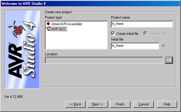
When learning any new programming language your first program is usually the classic "Hello World!" program. We will do something similar only due to the abilities of the hardware we will write a more primitive "Hello World!" program that I call "Hi There!". Instead of outputting the text "Hello World!" we will have an LED blink at us.
Figure 1
Figure 2
Here is the code to "hi_there.c":
// hi_there.c
// A simple program that toggles PB0

#include <avr/io.h>

void delay (void); // Delay function prototype

int main (void)
{
	DDRB	= 0x1F; // Set all pins as output except RESET (PB5)
	PORTB	= 0x20; // Set all output pins low. Enable pull-up on RESET (PB5)

	while(1) // Main Loop
	{
	   PORTB ^= 0x01 << PB0; // Toggle pin state
	   //delay(); // Delay loop. Comment this out for faster simulation.
	}

	return 0;
}

void delay (void)
{
	unsigned int counter = 10000; // Declare counter with intial value of 10000
	while (counter--); // Decrement counter until zero
}
Enter the code into the editor. You can either cut and paste the code or for the lazy here is the downloadable code file:
| Function | Button | Short Cut |
| Build |  |
F7 |
| Build and Run |  |
CTRL + F7 |
| Start |  |
N/A |
| Stop |  |
N/A |
| Run |  |
F5 |
| Break |  |
CTRL + F5 |
| Step Into |  |
Shift + F5 |
| Autostep |  |
Alt + F5 |
Tip: To view the port bit numbers in the "I/O View" right click and select view bit numbers.
With our code written it is time to compile it. Hit the build button (F7). Check to see if any errors came about. If so then correct the errors else you are ready to run the simulator.
Press the play button and the simulator will load the resulting hex file the compiler just made from our code. Click on the "I/O View" tab information window (Figure 3) so you can see the PORTB information. This will let you see what is happening on PORTB. You can now have the simulator run through the code either automatically using the "autostep" function (Alt+F5) or you can manually step (F11) through the code by hand. Watch as the arrow steps through the code. Each step represents roughly a clock cycle in the processor. Notice the 0 in PORTB toggles on (Figure 4) and off (Figure 5). If you are running in autostep mode you can pause the code execution with the break button (Ctrl+F5). You now have a successfully simulated "Hi There!".
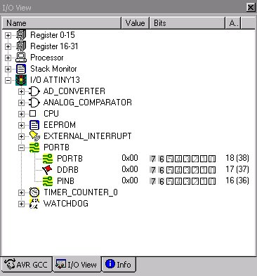
Figure 3
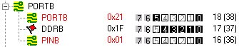 Figure 4 |
 Figure 5 |
Tip: You can compile and load the file into the simulator in one click by using the "build and run" button (Ctrl+F7).
Now that we have seen the program run in the simulator lets get the software into the uC and run it for real. Take one of the jumper wires that came with the kit and hook up the header PB0 under PORTB to header LED0 under LEDS. This will connect the processor's PB0 pin to LED0 on the board so we can observe the pin toggling.
Now hold on a sec. When we simulated the code it ran at a speed that we could observe PB0 toggling. Remember I said that in the simulator each step represents roughly a clock cycle in the processor. The processor runs at millions of cycles per second. If we load the code as is PB0 would toggle at a rate so fast we would not be able to see it unless we used an oscilloscope. The lesson to be learned here is the simulator does not simulate the processor in real time.
We need to put in some kind of hold for a duration of time between toggles so we can observe with the naked eye the current state. Time to uncomment the "delay()" line and recompile. This will put a long enough delay between toggle cycles that we can observe PB0's state with the naked eye when running on the uC. The delay loop is just a simple decrementing counter.
Note: I commented out the "delay()" function originally to speed up the simulator and so you didn't have to sit there waiting for the delay function to complete.
Tip: If you wish you can simulate the recompiled version to see the delay function work. You can even put a "watch" on the counter variable by right clicking on the variable name with the mouse and selecting "Add Watch" so as to observe the counter decrementing in the "watch window".
Back to the uC. Once you have recompiled the code go ahead and turn the STK500 on, connect with it using AVR Studio, and program the uC. Once programmed the Tiny13 will start blinking LED0 on the board.
Tip: To save you from having to run around and find the hex file you can select under the "Flash" section the "Use Current Simulator/Emulator FLASH Memory" option. This will ensure that you load the code that you just simulated into the uC.
Congratulations!!! You now have your first working "Hi There!" program.
On to bigger things.
Your Tone God,
Andrew