Simple Star Trek Ship Tutorial 3
page 2
the wing


We just finished the nacelle. Look at the side view and rotate it to match the schematic . see picture to the right.
This picture is two views pasted together.

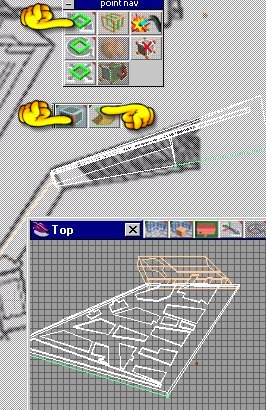
In the top view select a box shape. Change its shape by shrinking and move to location as seen on picture . Then using face select tool , select the top of the box .We are going to move or shape the box to make the lower section of the wing.
I am going to make the wing in two parts .
Drag the edge to match the schematic using top and side view.
There are several ways to add detail. 1. you can cut sections out of areasor 2. you can add layers ontop of sections or 3. you could use a texture map and paint on the details.
Now comes a time to make a decision. Do I model the parts with cutouts or use texture mapping?
For this tutorial we Cut.

I will show you some tricks as to how and when to cut (subtract one object from another to make a new shape).
This first part is easy .
Using the box shape make 2 thin boxes and possiton them as shown , paint them dark green.Make a fat box and paint it black , position as shown.Use both the top and side view to stretch your cut boxes

The next part of the wing is at an angle .
So what I do is select a flat plate , I then rotate it to match the angle of the surface I want(see hand) , then UV project the image of the background on it . Now rotate the plate horizontal and render a new picture which I call detail 1 .
I then select detail 1 as my background.

I use the line poly tool to trace out the next section of the wing. Once happy , I select that area and sweep upward.See picture on the right.
I leave this flat(horizontal) and we will cut out the grooves. Before we start cutting paint the new shape with (green_panel) and save.

Use the line poly tool and trace out all the sections as seen on the background. Then glue them all together.
I then select these 'cutout sections' with the point/face edit tool and sweep upward , we are making a new cutting tool .
Save it , call it cutter 1 .We will be cutting on the top and the bottem of this wing section.Paint these cutout blocks dark green.
You can get as detailed as you like with these cutouts, but.... .
DANGER DANGER Will Robinson
Don't cut too often , I try to glue all my cutout blocks together and make one cut . Sometimes if you cut a shape several times , it just goes away or desides to move around with out your help .
If you cut too often on one shape and then save , the object might not be where you left it , it might change shapes or even change itself.
Now you could spend hours and hours making cutout tools for more and more detail.
That is purely up to you .
This is called a cut corrupted mesh (Calagori says they are working on it) LOL yea right. The point is , save often and cut once.
Remeber the old saying 'Measure twice , cut once'

After you cut with your object subtract tool(see hand) , top and bottem , it should look something like this:
Now rotate this part of the wing and use the point edit/line edit tool.

We will select the face furthest from the nacelle.Far left picture.
Once selected , use the modifier tool and stretch to fit the schematic.
All we are doing is fattening the wing up
Rotate the edge down to match the schematic.
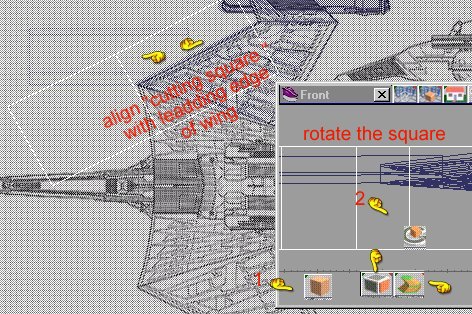
Then reload your cutter tool and flip it upside down .Align with the new bottem of the wing . We are going to cut the bottem section just like we did the top.See picture directly above this paragraph.
After you cut , you got it SAVE


It you wish , you can do a partial render now , just to see what it looks like.Under the render tool (See hand)if you right click you get a menu dropdown , this little tool lets you outline a certain area to render in stead of the whole image.

If you look on the leading edge of the wing you notice a darkened area.
Pic to the right.
Might be some kind of cooling inlet or what ever.
We must make a cutout to see it .I use the spline tool(see hand 3) .In the top view we trace out the shape , then select the face(hand 2) of the shape we just made a sweep(hand 1) upwards.
Select the shape and rotate it 90 degrees .
Now select a box shape (see pic on the left) rotate the box so it aligns with the leading edge of the wing.
We will use this new box to cut the shape you just made .
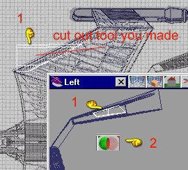
Then the new shape will be used to cut a 'cooling duct' in our wing.
This new cutting tool (see pic on the right) will be moved as shown
in the picture.
We will use the object subtract tool (see hand 2)
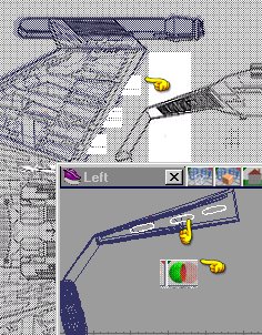
That was the leading edge.
Next we cut on the trailing edge.

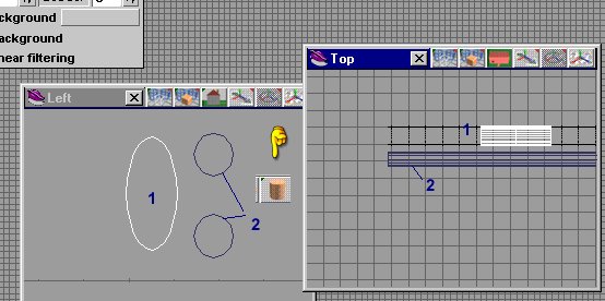
Select the spline tool and draw a oval . Select that face (hand 1) and sweep (hand 2)
See pic on the left.
Rotate it 90 degrees.
Do the same as we did with the leading edge.
Select a square or box . Rotate it to align with the trailing edge and cut the spline shape with the object subtract tool (see hand). see picture below right.
Now copy this new cutting shape 3 times and possition as shown on the drawing to the left. Glue them all together. We are going to cut 3 little exhause ports on the trailing edge . After you get the cutting tool in position use the object subtract tool to cut the wing with this shape. See picture below left.

Remember; at any time , if you want to see any of these pictures a little more clearer.Right click on the picture and select view image.
Select the new wing section , glue it to the lower wing section and then save.
We will only make one wing . Latter we will copy it and make a mirror image for the other side.
Now we will make the upper shoulder part of the wing.
we will make it the same way that we made the lower part of the wing
Start out by tracing the upper section using spline tool(see hand).

Select the face (using the point/facetool)(see hand)

We sweep upward , then twist the face to match the schematic.See the little picture in the picture to the left.
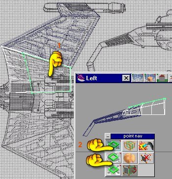
Now select the top edge(hand 1) again and move it to the right and shrink it.
We want to give the leading edge a ramp or wedge shape.(See hand 2/3)
The last section we cut . We all saw how to do that . So this section we will add sections on top instead of cutting.Select the poly line tool and trace out a section . Then select the new section with the face /point edit tool and rotate to match the schematic . See picture below.
You will use the nav point tool (see hands)
After you are happy with the shape , copy it and move it as show in the picture to the right, or make new shapes if the schematic shows them. Glue them all together and paint these sections dark green .See picture to the right.

Sometimes I use a cammera to ensure that I have the new sections aliened with the lower section.See picture below.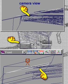
You can see I am making these new sections for the front part of the wing too. The sloped part.

Once you are happy , glue them all together.
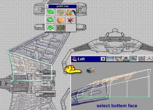
Next we select the lower face of the wing.

Sweep using the face select tool and the sweep tool as shown. .
I then select the line edit tool and do some minor adjustments , you may not have to do this , but if you are not happy , move it .
You did just save right?
Not shown in my pictures is a techneque which I often use .
That is to select each face and then select the bevel tool , this give some of the faces a little 'height'.
I then paint thes raised surfaces with a darker color to hight light the edges.
This type of ship has 4 disruptors . So , we have to make them. Nothing exoic.
Select the cylinder(tube) shape , in fact make a few of these and shrink some to make them look like the image below.
Paint these using green and copper (see picturebelow)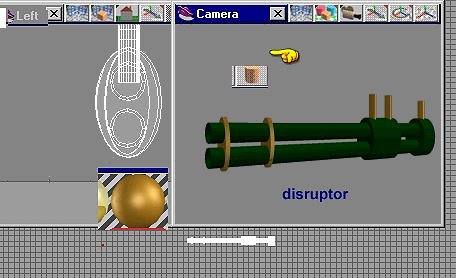
Glue all the cylinder together and save as Disruptor. Remember there are 4 on this ship.
Shrink your disruptor and place on the wing model per schematic (see picture below right.) 
Glue all these together , and save .
Your model should look like this:

Now you have a wing , SAVE IT
Do I say that enough?
next comes the main hull of the ship . That part will be on page three.
Page Three