Star Trek Ship Tutorial 3
page 5
Details
 Ref picture on the right.
Use the poly spline line tool and trace the shape using the top view.
I paint this an orange color. Then I use the face edit tool and bevel the shape. Then select the top face and paint it dark red.
I then like to bevel the top and bottem edges.
Ref picture on the right.
Use the poly spline line tool and trace the shape using the top view.
I paint this an orange color. Then I use the face edit tool and bevel the shape. Then select the top face and paint it dark red.
I then like to bevel the top and bottem edges.

Select the spline tool and draw a circle . copy it and subtract one from the other to form a ring. paint the ring and place it as shown on picture to the left.
 Remeber the command section; on the left side on the top
we made one funny shaped square shape . It was only on the left side .
Shrink the new moto mesh and place it on the side of that funny shaped
square section on the command section ,see picture on the left.
Remeber the command section; on the left side on the top
we made one funny shaped square shape . It was only on the left side .
Shrink the new moto mesh and place it on the side of that funny shaped
square section on the command section ,see picture on the left.
On the long skinny part of the neck connecting the command section to the engineering sedtion , there is a raised area .
Load the moto again and place it as shown , left and right side.
See picture below.
On the side of the main part of the ship there is a square section which we painted black.
On the ship this area is a heat exhanger with cooling vains.
This section is on the side of the area where the shuttle bays and or the cargo section.

Lets add detail here. Make a box and stretch it , then rotate as indicated in the picture on the right.
Paint it black. Copy this box and shrink . paint it off black with some shiny to it. Copy it several times and place (as vanes on the big box).
See picture below (hands).


Glue all the boxes together .Copy the boxes
and inverse copy , place the new one on the oposite side. See picture on the right.
Now it is time that we deside on a name for our ship .
It is Klingon so , it has to have a Klingon name .
For this tutorial we shall call our ship the "B'Moth"
Officially it will be the ' IKS B'Moth '.
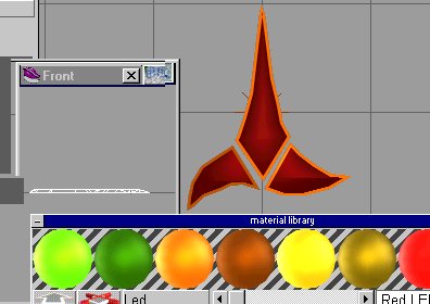
There are lots of Klingon Sites about .I went to one and found this simple chart (see chart below left).

So in Klingon B'Moth is :

In your paint program make a new image .
With this as the middle on a white background , save it as a TGA file
.We will use the UV projector to do this .
This next Part is for use with TS 3 .
On Klingon ships they place the name of thier ships in two places.
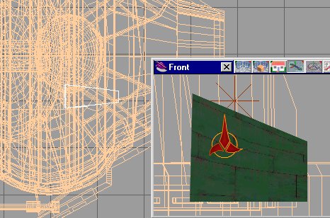
The primary place is along the trailing edge of the left wing.
So: Go to the model , go down in Hyarchy till you get to the left wing ,Just the wing. For today , I will copy it and save as lwing.cob.
Errase the rest of the ship . We are going to do this for simplicity.
When we are done we will install this new wing (with markings) as a replacement to the left wing.
So with only the left wing showing , First select the UV tool.
Select the object and select the uv tool (see pictureon right).
The tool looks like a green square , select it an a drop down menue appears. I shall select the 1st type, the flat plate.

 Using the normal nave tools (see picture on the right) move or rotate the UV projection so it is aligned with the trailing edge of the wing.Nit the apply button.
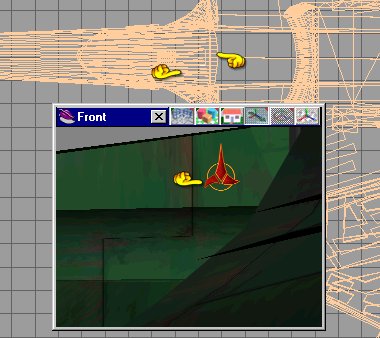
 Now select the UV tool again, this time the lower most tool will be active (see the hands).Click on it . A new pop down window appears. Select new . A new UV field will appear, but this time it is controled by the little controls on the pop down menue.
NOTE:Sometimes thes tools work backwards , push the tool up , the UV goes sideways. It's annoying as heck
Now select the UV tool again, this time the lower most tool will be active (see the hands).Click on it . A new pop down window appears. Select new . A new UV field will appear, but this time it is controled by the little controls on the pop down menue.
NOTE:Sometimes thes tools work backwards , push the tool up , the UV goes sideways. It's annoying as heck
 See picture on the left.
 For TS 3
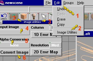
Select edit (hand 1) Select Image Utilities
(hand 2) A new pop up window will appear (hand 3) .
In Hand 4 location , is a drop down where you select the image you want.
We made the image a tgr file. Select it. Also selct it with a paint brush, slide the transparancy bar to the full up position.button under hand 5.I select eighter top corner or white. When I Select the control at (Hand 6)it converts the file to a see thru image.
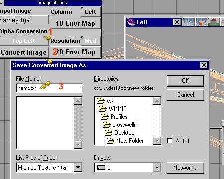
It then makes a new file called a txt file .
So I have a Name.tga file I change to a name.txt file.
 See picture on the right . Step by step , After converting the image
(hand 1) Selct a paint brush and push in the button at hand 2.
Make sure the slider for trancparency is all the way up (hand 3).
Push in the image select tool(hand 4) , selct the image you want (hand 5) the new txt file. Selct overlay (hand 6).Your image should look like this (see hand 7).Push in the funnel button(hand 8).
The new (sub UV projection should appear (hand 9).
Whew , simpler to do than to explain.
See picture on the right . Step by step , After converting the image
(hand 1) Selct a paint brush and push in the button at hand 2.
Make sure the slider for trancparency is all the way up (hand 3).
Push in the image select tool(hand 4) , selct the image you want (hand 5) the new txt file. Selct overlay (hand 6).Your image should look like this (see hand 7).Push in the funnel button(hand 8).
The new (sub UV projection should appear (hand 9).
Whew , simpler to do than to explain.
Save this new wing . Reload the old wing or ship model . They should overlap. Select the old model and step down in Hyarcy till the old wing is all that is up. Delete it. Glue in the new one.
Save .
This is how you do it in TS 4
 Just like discribed in the TS 3 section , I go down in Hyarchy till I have just the section I want to apply a UV image on.I apply a UV map.
Usually the flat plane one . The big differnece is in the paint tools.
Just like discribed in the TS 3 section , I go down in Hyarchy till I have just the section I want to apply a UV image on.I apply a UV map.
Usually the flat plane one . The big differnece is in the paint tools.

Look at the picture to the left.When we select any paint tool a shader menue appears. Selct the top left ball(hand 1).
Then a pop down menu appears , select texture map(hand 2). Select what you want (see hand 3).

Picture on the right. Select the left lower ball (reflectance control). Selct constant on the pop down menu(hand 2).

Next selct the transparancy control ,( Hand 1) picture to the left (top right hand ball. Select it and then select plain transparancy(hand 2)
Note in the picture on the right,right click the funnel paint control(hand 2) picture to the right, to varify your image is still selcted (see hand 1) . Now push the funnel paint button and your UV section should become visable (see hand 3) . Do a render to check if you want.

Save this new wing . Reload the old wing or ship model . They should overlap. Select the old model and step down in Hyarcy till the old wing is all that is up. Delete it. Glue in the new one.
Save .
LIGHTS
Select a low poly cylinder. Paint it bright red .
 See picture on the right.Stretch them a bit, long wise.I chose to place lights on the command section (see picture below on the left). Place some more lights on the wings and near the shuttle bays
or where ever you want/need them.
See picture on the right.Stretch them a bit, long wise.I chose to place lights on the command section (see picture below on the left). Place some more lights on the wings and near the shuttle bays
or where ever you want/need them.

This version of the ship has 6 Disruptors , we have installed 4 .
The next two are smaller , and for area defense .
To make them selct a square and select one face . shrink it.
Now select a cylinder . Stretch it , see picture on the right.
. See picture on the left.
Move the tube to the middle of the pyramid . Paint the pyramid with green panel and the cone with green . See picture on the left below.

Place these small disrubtors as shown on the picture on the right.

Note these are small and there are 2, one on each side.
Now you have the details and a complete ship mesh , SAVE IT
Do I say that enough?
Enjoy the model and your adventure making it.