 |
|
|
|
|
|
|
|
|
|
|
|
|
|
|
|
|
|
|
|
|
|
|
|
|
|
|
|
|
|
|
|
|
|
|
|
|
|
|
|
|
|
SE-R Homebrew CAI Install |
|
|
|
< -------------------------------------------------------------------------------------------------------------------> |
|
|
|
 |
|
|
 |
|
|
|
|
 |
|
|
|
Step 1: Supplies: 45 degree 3" PVC elbow X 4, 3" PVC pipe X ~5.5", chopping board X 1, 3" hubless rubber boot X 2, 3" screw clamp X 4, thread sealant/glue, caulking, air conditioning sheet filter, and an RU-3550 K&N Filter.
The chopping board (blue) was cut and fashioned as shown to fit the MAF sensor manifold. An air bypass valve was cut into the PVC pipe with a rotary tool and a bit a time. Each of the four holes is approximately 2" X 1.5" and is beveled for smoother airflow. A rubber boot was fitted over the bypass and slant-cut against airflow in a crescent shape. The resulting concave lip was pressed into the intake, creating a negative pressure sensitive port. The boot was then secured with two screw clamps. |
|
|
|
|
|
|
|
|
|
|
|
|
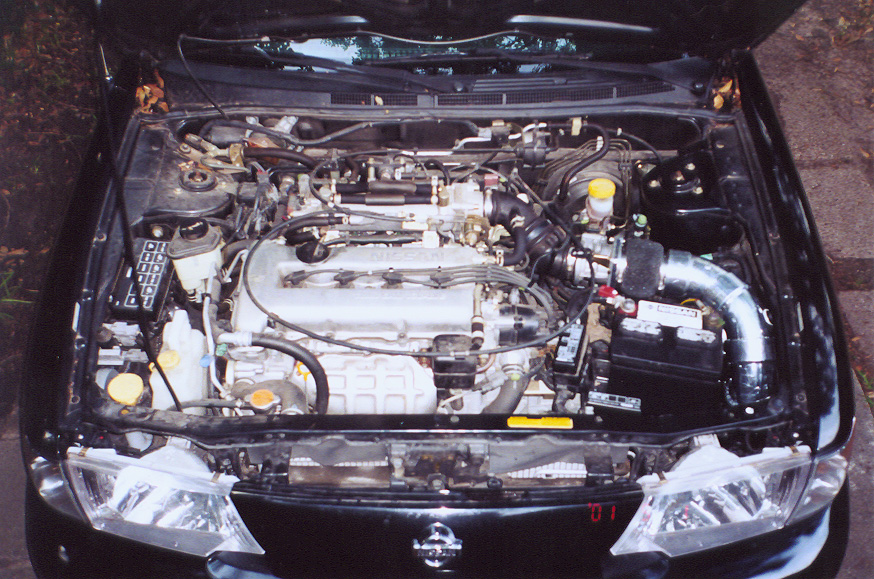
Step 3: This is the prefitting of the homebrew CAI. All parts were fitted together without glue. After the desired position was obtained, the alignment of the pieces was marked. The battery was moved slightly to the left to give the CAI more room. The bottom fitting (only the lip is visible) is a 45 degree elbow pointed forward toward the back of the left fog light. |
|
|
|
|
|
|
|
Step 1.5: The manifold adaptor was secured to the air bypass assembly by predrilling 1" holes into the adaptor and PVC, gluing the two together with epoxy, and then driving 1" nails into the predrilled holes. |
|
|
|
|
|
|
|
|
|
|
|
 |
|
|
|
|
|
|
|
 |
|
|
|
|
|
|
|
|
Step 2: The resonator box was removed. The oval whole in the chassis leading to the resonator was expanded to a 3.5" diameter circle with a rotary tool with cutoff disk attachment. Cutting from the buttom with the car elevated is the easiest way to do this. (This whole should be a little larger than 3.5" to accomodate the elbow.) The battery tray must also be trimmed in order to fit the elbow. The whole was then cleaned, painted, and coated with an acrylic sealant to prevent corrosion. |
|
|
|
|
|
|
|
|
|
|
|
|
Step 4: The finished homebrew CAI. The pipes were glued together with tread sealant. The gaps at the pipe junctions inside the tube were filled with caulking and smoothed out. Uneven pieces of caulking were removed when dry. A 0.75" hole was drilled into the side of the third elbow from the filter for the air temperature sensor. The entire assembly was then wrapped with foil tape and smoothed out. Two layers of foam were cut to size, treated with filter oil, wrapped around the bypass valve and secured by screw clamps. |
|
|
|
|
|
|
|
|
|
 |
|
|
|
|
|
|
|
|
|
|
|
|
Step 5: The stock air filter box and intake piping were removed, leaving the MAF sensor intact. The CAI was then inserted through the whole leading below and screwed into the MAF sensor with the existing bolts (6 mm nuts and thread lock are needed to secure the bolts). For me, the fit at the whole in the chassis was quite snug. I had to use considerable force and rocking to get it through. No rubber boot was needed to fill the space. We'll see how this works... The air temperature sensor was inserted and secured with a little bit of caulking. The filter was attached from below. |
|
|
|
|
|
 |
|
|
|
The finished product: Homebrew CAI. During a run to the local Walgreens to get these pictures developed, I performed a preliminary test of the CAI. The tone is for the most part normal under normal driving conditions (i.e. mild throttle). A deeper tone is achieved under moderate throttle. I haven't had a chance to go FOT with it yet, so I don't know whether there is significant power gain. Low end torque feels a slight bit higher, but it could be my imagination. I'm going to monitor the condition of the CAI for a few months to make sure everything holds up. Hopefully, the caulking can withstand the vibration. If not, I may need hints on cleaning the throttle body... I will continue my observations as they become available. Final cost: ~$80-90. |
|
|
|
my info: |
|
|
|
links: |
|
|
|
|
|
Name: |
|
Your Name |
|
SE-R.net |
|
|
|
|
|
Email: |
|
email@yahoo.com |
|
|
|
|
The SE-R Mailing List |
|
|
|
|
|
Yahoo! Photos |
|
|
 |
|
|
|
|
|
|
Yahoo! Greetings |
|
|
|
|
|
< -------------------------------------------------------------------------------------------------------------------> |
|
|
|

|
|
|
|
