BIGGER SUPERCHARGER PULLEYS
The purpose of an oversized supercharger pulley to gear up the supercharger so at any given rpm the supercharger is spinning faster, and therefore making more boost and more power ( well in theory )
There are a range of supercharger pulleys
available for the ZE engine ranging from the HKS one at10mm oversized to the
CUSCO one at 25mm oversized. BLITZ Also makes one at 15mm oversized.
I would recommend that you don't buy any of theirs due to there cost. I would
recommend you get a machine shop to just modify your stock one which shouldn't
be to hard. I would also warn against any aluminium pulleys. I had a aluminium
pulley and it turned out to be to soft and began to wobble after a short time.
 As
As for expected results from running the bigger pulleys, with a 25mm oversized pulley
I saw a maximum of 13.4 psi in 4th gear. The car felt a lot fast than it did
in stock form. However in reality the car is not faster. What seems to be happening is
the car is retarding the ignition timing due to the hot inlet temperatures created
by the over geared supercharger. To test this a added digital thermometer to
the outlet of my supercharger. Temperatures above 80 degrees C were the norm.
When going hard it would be in the area of 120 +. On a number of occasions I
got the temp off the scale which max'd out at 150 degrees C. I am currently
running the stock pulley again and the car feels faster on the open road than
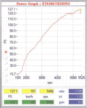
it did with the bigger pulley. I also got the car dyno'd it made 96kw at 5,500 (This was with the 25mm over sized pulley ).
At 5,500 rpm there is a steep drop off in power it would seem adding the pulley increase power
by about 10kw's at the wheels but at 1,000 rpm less than with a stock pulley. This woulld seem to be
the reason why a stock and modded ZE's seem to have the same performace after 1st
gear. If your going to get a bigger you MUST buy a bigger front mount intercooler
otherwise don't bother ! With a bigger intercooler and supercharger pulley I
would expect to see good power gains. However i can't see how anyone could realistically make big power with the 25mm over sized pulley without the largest of front mounted intercoolers. I'm personally going to go for ar 15mm over sized pulley and a reasonably large intecooler from a VR4 to keep things cool. I hope after his my car will finally brake into the 100 + kw's at the wheels
As
As for expected results from running the bigger pulleys, with a 25mm oversized pulley
I saw a maximum of 13.4 psi in 4th gear. The car felt a lot fast than it did
in stock form. However in reality the car is not faster. What seems to be happening is
the car is retarding the ignition timing due to the hot inlet temperatures created
by the over geared supercharger. To test this a added digital thermometer to
the outlet of my supercharger. Temperatures above 80 degrees C were the norm.
When going hard it would be in the area of 120 +. On a number of occasions I
got the temp off the scale which max'd out at 150 degrees C. I am currently
running the stock pulley again and the car feels faster on the open road than
it did with the bigger pulley. I also got the car dyno'd it made 96kw at 5,500 (This was with the 25mm over sized pulley ).
At 5,500 rpm there is a steep drop off in power it would seem adding the pulley increase power
by about 10kw's at the wheels but at 1,000 rpm less than with a stock pulley. This woulld seem to be
the reason why a stock and modded ZE's seem to have the same performace after 1st
gear. If your going to get a bigger you MUST buy a bigger front mount intercooler
otherwise don't bother ! With a bigger intercooler and supercharger pulley I
would expect to see good power gains. However i can't see how anyone could realistically make big power with the 25mm over sized pulley without the largest of front mounted intercoolers. I'm personally going to go for ar 15mm over sized pulley and a reasonably large intecooler from a VR4 to keep things cool. I hope after his my car will finally brake into the 100 + kw's at the wheels
EXTRACTORS , EXHAUST MANIFOLD
The most common question asked about
extractors in regards to the ZE engine is will the 20v extractors bolt straight
up to the ZE. The answer to this question seems to be NO but that's ok cause
who wants them anyway .There are two kinds of extractors available 4 into 1
and 4 into 2 into 1. The 4,1 extractors generally produce better top end power
over 4,2,1 at the expense of bottom end power. Which ones you choose is up to
you I would recommend a good sized diameter primary pipe for good top end power.
INJECTORS
From what I have read the ZE injectors
seem to be ok up to running 280 to 300hp . From the testing I have done it would
seem that at no stage do you 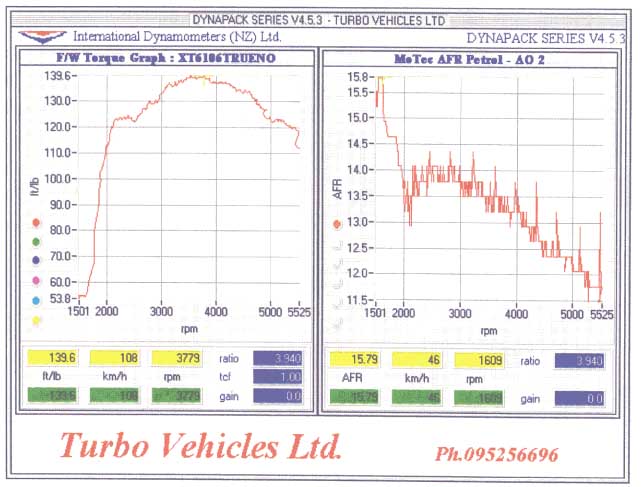 need
to add bigger fuel pumps and more injectors or any kind of fuel management system
(well on my 1991 map ZE with just more boost added ). The car does NOT run lean
up top when you increase the boost. However there is a lean spot down lower
which an engine management system of some kind would fix.
need
to add bigger fuel pumps and more injectors or any kind of fuel management system
(well on my 1991 map ZE with just more boost added ). The car does NOT run lean
up top when you increase the boost. However there is a lean spot down lower
which an engine management system of some kind would fix.
CAM COVER PRESSURE RELIEF MOD
On the 4A-GZE there is a cam cover pressure relief pipe which sucks air/oil
out of the top of the cam cover to prevent excess pressure being built up. This
pipe runs form the cam cover to the aluminium throttle body inlet pipe ( 1 ).
You should put a plug in the inlet side (1) so no air can get in or out. On
the cam cover side put a breather ( a small air filter ) to still let pressure
out of the cam cover
 Why
would you want to do this you ask ?
Why
would you want to do this you ask ?
Well as you can imagine the cam cover is
under pressure and the inlet is under vacuum ( the supercharge is sucking in
air throw the throttle body ) So higher the boost pressure the more vacuum you
will have in the inlet pipe. Because of this pressure difference the air/oil
will be sucked out the cam cover and go thought inlet pipes, supercharger, inter-cooler
pipes and into the combustion camber. Having oil in the combustion camber will
cause smoke and a lack of power also you will use more oil. Because of the oil
going though the throttle body and pipes this causes oil and dirt to build up
and cause a MASSIVE restriction to the inlet pipes and there for rob you of
power. After performing this mod you will be able to clean the inlet pipes,
throttle body and butter fly with a clean cloth and they should stay clean.
INLET MODS
To get more power out of any car all you
need is more fuel and more air. Getting more fuel is the simple one, but getting
more air into each cylinder is the hard one. When looking at the 4A-GZE inlet
pipes it becomes very apparent that there could be a lot of work done to improve
flow and there for power. The simplest way is to just improve on the comes standard
with the car. To improve flow rates of the pipes I removed all the inlet pipes
and supercharger pipes and using a titanium cutting tool ( which I got from
place makers ) and a Dremal I grounded al the shape edges off all the pipes
and made them all nice curves which flow considerably better the sharp edges.
The only half difficult pipe to do is the plastic pipe which is pop riveted
to the inter-cooler. These rivets need to be drilled out in order to remove
it.
One of the biggest restriction to the inlet
is the aluminium pipe which sits on top of the throttle body and comes after
the plastic air filter pipes. ANY modifications to this pipe will give you big
gains in power due to the bad design of this pipe. One of the ways I made this
pipe flow more air was to sand it down with 600 grit sand paper. Sanding pipes
down with 600 grit will allow them to flow better because it will be smother
than standard and there for flow better ( you don't want a polished surfaces
as they flow less ).
Another big restriction to this pipe is the fact that it is not round and it
get narrower on both sides of the pipe just as it turns the 90 degree corner
I sanded this back using a sanding bit for my Dremal. Now the pipe is much rounder
now. Because of these mods you should notice an increase in boost and power
( well I did with a 170mm pulley ).
Another way I increase the flow thought this pipe was to pipe air into the back of it. There are already two pipes going into the this inlet pipe which can be used to pipe more air into the inlet pipe. If you have already done the cam cover pressure relief mod and blocked off the inlet side of this pipe it can be unblocked and piped using a ½ inch pipe back into the less restrictive plastic inlet pipe behind the air filter. This can also be done to the ¼ inch Supercharge bearing relief pipe which plugs into the back of the aluminium pipe. I just put a T joint in it to still keep the supercharge bearing relief but to allow this pipe to flow air into the inlet as well . I put the other end of this pipe also into the plastic pipe behind the air filter to allow air to flow though it
Ultimately thought you should replace this pipe with a mandrel bent pipe you should also replace the plastic inter cooler pipe as well.
THROTTLE BODY MODS
The throttle body is a major restriction and should be bored out as soon possible, it should take a 3mm increase in bore ( but I will have to look into this more before I do it )
ARE YOU HAVING PROBLEMS CHANGING GEARS IN YOUR AE101 ?
It is a very common problem with AE101's. If you are having problems changing into 2nd and 5th you can fix this in 2 minutes. All you need to do is lift up the leather boot ( around your gear leaver ) and you will see three ten mm bolts just loosen these and push it to the right ( toward the driver , in a right had drive car ) and then tighten them again. This will not fix the problem totally because as you can imagine you have damaged the syncro cones but it will be a lot better. If you are wondering what causes the gear leaver to move to the left and therefore creating this problem it is from excessive reversing ! yes reversing.
REMOVING THE SPEED LIMITER
To remove the speed limiter all you need to do is to cut the speed sensor wire from your compter pin 9 ( violet and white ) of the 22 ( the right hand one ) pin connector . You will find your compter on the floor behind the stereo. Since i did this i have noticed that every now and again the engine light comes on. I do not take responsibility if this damages you engine. Do this at your own risk, but i must add that i have made this modification to my car. This mod also works on 20 valve but the wire is different. To get these diagrams go to CLUB 4AG .
If you screw your car it is your fault so check out these mods for yours dont just blindly do them.
Copyright (C) 1996, All Rights Reserved.
David Kucharczyk (ssr@netcom.com)
The Toyota 4A-GZE motor was used in the 86-89 MR2 Supercharged edition MR2s. The motor is a modified 4-AGE unit coupled to an electronically engaged roots type supercharger (manufacturer currently unverified) and a Nippon Denso air-to-air intercooler. Static compression ratio of the motor was dropped from 9.4:1 to 8.0:1. The camshafts have less duration and overlap than the normally aspirated 4-AGE. Boost level is set at 8 PSI and achieved at 4000 RPM and higher, however the supercharger creates usable boost from idle through redline.
The supercharger is driven by a serpentine belt off of the crankshaft and shares it’s drive belt with the water pump. An electromagnetic clutch is installed on the supercharger, allowing it to freewheel when it is not needed. The clutch is controled by the engine’s electronic control unit (ECU). A combination blow-off/bypass valve is provided to route air around the supercharger when the clutch is disengaged or when boost exceeds 8 PSI (nominal). The valve is operated by manifold vacuum/pressure. The ECU has the ability to force the bypass closed via an electronic vacuum cut off solenoid valve.
The rear engine cover was modified to increase the height of the vents to clear the intercooler. The passenger side engine cover vent was closed off and the driver side vent had moulding added on the inside to seal against the top of the intercooler. (Swop those around for us right hand drive owners - Ed.) The engine cover is also made from ABS plastic rather than stamped steel.
A green light emitting diode indicator located on the tachometer and labled "Supercharger" is activated by the ECU whenever intake manifold pressure is positive. An engine knock sensor and a fuel octane selection switch were also added.
The supercharger is a roots type unit, manufacturer is unknown at this time. The lower vane is driven by the pully and drives the upper vane via gears located in the rear of the housing. The gears are run in Toyota supercharger oil, Toyota part number 08885-80108. The lubricant costs about $50 for 50ml. Total gearhousing capacity is 130ml.
Two special tools are required for disassmbly of the supercharger; SST 09504-00011 for keeping the pully from rotating while you undo the nut that holds the clutch hub to the supercharger. If you have an impact wrench you might be able to get by without this for removal. However you will still need something to hold the pully when you tighten the nut down upon re-assembly. SST 09814-22010 for removing the ring nut that holds the clutch pully on. You can’t get by without this short of having a set of ring nut sockets or custom building the equivalent tool.
Vent holes are placed at three points in the housing. One in the rear gear housing and one to each of the shaft ends of the vanes on the front of the supercharger. The vents are all connected together via external metal tubes and hosing. An air valve is connected to all the vents which can purge them to the intake system after the airflow meter but before the throttle body.
The supercharger adds heat to the intake charge both by conduction of housing heat since the supercharger is bolted onto the engine and also by pressurizing the intake charge. With the bypass valve open and the supercharger disengaged the intake system raises the intake charge temperature by about 16.5oC once everything is up to operating temperature. Running under full boost with an outside air temperature of 10oC the air temperature of the SC outlet can get as high as 132oC.
The supercharger clutch works in the same way as an air conditioning compressor clutch. The pully itself spins freely on the supercharger input shaft. A coil of wire sits behind the pully and a metal disc sits in front. The front disc is connected to the actual input shaft of the supercharger. When the coil is engergized, the disc is drawn against the rotating pully and they then rotate together as a unit untill the coil is de-energized.
The ECU engages the supercharger based on intake manifold vacuum. When the vacuum drops below 8" the supercharger clutch is engaged. The clutch stays on untill the intake manifold vacuum has risen to over 10" for a period of 5 seconds. This time delay was added to avoid cycling of the clutch during shifts and momentary throttle transitions.
The clutch is operated by the ECU via a relay that lives in the rear trunk right next to the ECU unit itself. Both are located in the center of the engine/trunk behind the pressboard trunk liner. The relay operates the clutch by grounding one side of the coil. The other side of the coil is connected to +12 volts when the ignition is in the ON position.
An interesting note is that the manifold vacuum will be low enough during highway driving that the SC clutch will stay engaged all the time. This typically occurs at speeds over 65 MPH. My cars milage ran around 26 miles per gallon under these conditions.
The air bypass valve (ABV) serves two functions. The first is to provide a route for air to bypass the supercharger when it is not spinning. The second is to act as a blow-off valve when boost exceeds aproximately 8 PSI. The blow off point varies significantly between cars from 8 to 10 PSI.
The valve is attached to the rear of the supercharger and is closed when the car is not running. It is in effect, a spring loaded plunger that blocks a port that runs from the supercharger inlet to the outlet. When the intake manifold pressure on the plunger exceeds the spring pressure, the valve starts to open, allowing the outlet side to discharge some of it’s air back into the inlet. This sets the maximum boost pressure.
The bypass function is achived by adding a vacuum operated diaphram on the back side of the valve, which pulls the valve open. As soon as the car turns over, intake manifold vacuum is created, which is routed to the diaphram and opens the bypass port. As the throttle is opened, vacuum in the intake manifold drops and the valve starts to close. The valve starts closing around 4-5" of intake manifold vacuum and is fully closed by 1-2". Since the computer has activated the SC clutch when intake vacuum dropped to 8", the supercharger starts spinning while the bypass valve is still open. The valve starts closing with the supercharger already spinning thus creating a gradual smooth transition from an open to closed intake system.
The computer also controls a solenoid valve that vents the vacuum diaphram on the air bypass valve to outside air. By doing this, the computer can cause the ABV to close regardless of intake manifold vacuum. This valve opens as soon as there is positive pressure in the intake, thus keeping the diaphram from working in reverse and pushing the ABV valve closed more tightly as intake pressure increases. The computer also holds the ABV closed this way when there is sudden vacuum in the intake, such as when you release the throttle during a shift. This way the intake system stays sealed to the supercharger while you shift and the system does not have to re-seal when you step on the gas again. After several seconds of closed throttle (constant vacuum in the intake), the computer releases the valve and disengages the supercharger.
Interestingly, connecting the diaphram directly to the intake system, thus causing the valve to cycle open during shifts does not produce any noticable change in throttle response.
The intercooler is a Nippon Denso unit (part # 127100-0153) with 19 cores. Surface area is 200mm X 290mm with a depth of 65mm. The inlet and outlet tubes run the length of the intercooler and are 50mm in diameter.
When the car is in motion, air is drawn in via the side vent located on the passengers side of the car (driver’s side for us - Ed) and flows over the engine and out of the compartment via the intercooler. The side vent has positive pressure and the area over the engine cover has negative pressure.
At 65 MPH air entering the vent increases in temperature by about 5.5oC before reaching the intercooler. Suprisingly, the temperature increase stays below 8oC all the way down to 20 MPH or so. Increasing speed over 65 does not make a significant change.
At idle the underhood temperature rises to about 49oC at which point the fan installed in the side vent activates, bringing the temperature back down to about 38oC before shutting down. Note that the temperatures above were measured directly below the intercooler. Under hood temperatures vary considerably by location, for example the the fan sensor, which is located near the exhaust manifold activates at ~70oC and disengages at ~54oC.
Intake charge temperature drops between 55 and 28 degrees depending on conditions. When the intercooler is cold, full throttle opening will yield a 55 degree temperature drop which then falls back to a low of 28 degrees as the intercooler itself heats up. 10 seconds after 1/8 throttle to full throttle opening the intercooler temperature drop is down to 39 degrees and within 30 seconds falls to 33 degrees, falling at a slower rate after that. Unfortunatly I did not have a data logger available at the time so I cannot provide any chart data. Actual outlet temperatures were as follows with an outside air temperature of 15oC.
Partial throttle cruise at 70MPH (SC
engaged, 8" vacuum) 38oC
Partial throttle cruise at 70MPH after full boost run 54oC
Idle, engine compartment fan on. 38oC
Maximum observed outlet temperature (long uphill run, 10 PSI) 93oC
The valve connects the supercharger gear case and end seals to the intake system before the throttle body. The valve is operated by the ECU. With the valve closed, pressure inside the vent system runs about 1/2 of the manifold pressure (or vacuum as the case may be).
I suspect the reason for this is to minimize the pressure differential between the vane end seals and the outside air. The ECU opens the vent line when manifold intake vacuum is betwen 0 and 3".
The knock sensor is attached to the engine block and sends the ECU an electrical signal that corresponds to engine vibration. The ECU filters the signal for frequencies of interest during a time window that is syncronized with crankshaft rotation to look for a characteristic signal that is produced during knocking.
If knocking is detected the ignition timing is backed off and then slowly returned to normal unless knocking is detected, in which case the cycle starts over. The detection time for knocking is in the 1-2 second range. I don’t have values for the amount of timing back-off or the return-to-normal speed. No attempt is made to drop the boost level when knocking is detected.
A switch is provided on the dashboard to select what type of gasoline is in use (high or low octane). Function is currently unknown, although changes in ignition timing would be expected.
The cost of Toyota SC lubricant is quite high. Other types of SC lubricants may work satisfactorily. Other places to try for lubricant are Ford (a roots type supercharger was used on the Thunderbird), GM (the Bonneville SC uses a roots supercharger) and any of the aftermarket roots supercharger manufacturers such as BI, Magnuson or Weiand. I expect any decent hypoid gear oil will work. I plan on using 90 weight synthetic gear oil the next time I am in the supercharger. After talking with several people who run roots type superchargers on race cars and change their gear oil frequently I could not find any reason why the Toyota unit would need something special. Maybe the $50 price tag is for the special syringe packaging and low volumes they sell. Or maybe they used whale oil or something...
Other sources for supercharger lubricants:
Weiand (213-225-4138)
Magnuson Products (805-642-8833)
3172 Bunsen Ave., Unit-K, Ventura, CA 93003.
146ml of NYE605 for $13 US.
Ford Motor Co.
General Motors Corp.
Numbers
Various raw data collected.
BHP: 145 at 6400 RPM
Torque: 140 ft/lbs at 4000 RPM
Source: Toyota
Curb Weight: 2605 lbs.
Weight Distribution: 44.5% Front / 55.5% Rear
Fuel Capacity: 10.8 US gallons
0-60 MPH Time: 6.5-7.0 seconds
Lateral Acceleration: .78-.80G
Source: Various car magazine test results.
Crank pulley/harmonic balancer diameters: 130mm alternator, 145mm supercharger.
Rim sizes: 14 X 6.0 inches (stock)
Alternate sizes: 15 X 7.0
Rim Offset: 33mm
Tire Sizes: 185/60/HR14 (stock)
Alternate sizes: 195/55/14, 205/55/14 (rear only), 205/50/14, 195/50/15
Tire circumference for best speedometer accuracy: 71" or 800mm (195/50/15)
Top Speed: 129 MPH headlights up, 132 MPH headlights down.
Boost:
3 PSI at 1000 RPM in 5th gear
6 PSI at 2000 RPM
7 PSI at 3000 RPM
8 PSI at 4000 RPM
8 PSI at 5000 RPM
8.25 PSI at 6000 RPM
RPM to speed ratio (ideal): 129.6 RPM = 1 MPH in 2nd gear.
HP measurements, 2nd gear, stock car, OAT: 15oC
000’s RPM MPH Run 1 (sec.) Run 2 (sec.)
RPM HP
2-3 14-22 0.99 0.98 2500 52
3-4 22-30 0.99 0.97 3500 75
4-5 30-38 0.90 1.00 4500 101
5-6 38-46 1.07 1.02 5500 114
6-7 46-54 1.17 1.17 6500 121
Source: Measured values.
This modification prevents the air bypass valve from acting like a blow off valve and disables the computers control over the ABV. Recomended for running higher than stock boost levels. Simple modification that involves running the vacuum hose from the ABV directly to the intake manifold and putting a cap on the line that ran from the VSV to the ABV. Only a T and vacuum cap are required.
( Ultrasonic2 )
ok it looks like this on my car the blue and red lines go from just behind the throttle body to the vsv on the far right take the bottem one and T join it into the top one (red) so it looks like the green line then cap off where you just unplugged the blue one from ( the green mark ) we used a bit of the pipe and srewwed a screw into it to cap it off. This car does not have the pipes because it is twincharged :-)

Replacement crankshaft pulley/harmonic balancer. Provides a higher drive ratio to the supercharger and water pump. Pully diameter is 10mm larger for the supercharger belt. Supercharger makes 2 PSI more boost with no other modifications except jumpering of the air bypass valve as noted above.
I have run my SC car with no filter element present and there was no change in boost level or measured HP. Clearly the filter is not the major restriction in a stock set up. Have not tested the HKS Powerflow unit.
Results from testing show very marginal improvements by adding a radiator type fan to the intercooler. The fan simply cannot generate enough pressure compared to the aerodynamics of the car to make a significant change in the flow through the intercooler. Intake charge temperature ran about 5.5 degrees lower with the fan operational. Usefull for pre-cooling the intercooler when stopped, but that’s about it.
If you install one, the fan should be set up to blow out through the top of the inercooler towards the rear deck lid. This is the natural airflow when the car is moving. Running in reverse caused higher intake charge temperatures as the fan slowed down the normal airflow over the intercooler. It has been suggested that a squirrel cage type blower can provide more pressure. Some bench tests with this fan type didn’t look very promising either. An air scoop on the drivers side of the car would probably work best short of relocating the intercooler.
No tests or data available.
Belt slippage is a known problem with the supercharger belt. Getting the tension set right by feel is very difficult as the belt runs are short, thus making the belt appear very tight when it isn’t. A tensioning gauge is highly recommended.
Belt slip manifests itself by a squealing or an air leaking type of sound over a particular RPM. The noise can be intermittent. A noticable drop in boost (around 2-3 PSI) is usually observed during the slip.
All prices are in US dollars.
HKS crank pulley: $315
Used supercharger: $400-1200
Picture 1

Looking at the supercharger from the top. Only the Air Bypass Valve (red and white sticker) is visible.

The radiator overflow tank has been removed. The Air Vent Control valve is the brown one on top of the supercharger with three hoses attached to it. The ABV diaphram control valve is the blue valve near the bottom with a hose running to the AVB. The brown valve in the very bottom vents the fuel pressure regulator’s compensation port to the atmosphere.
Permission is granted to reprint in any form for non-profit organizations only on the condition that copyright notice is retained.
Dave Kucharczyk (ssr@netcom.com)
CORRECTION:
One possible error in the article is the statement that the SC has different cams. It may actually use the same cams as a NA car. (?) Timing may be different.