
Blocking oscillator is a typical non-linear oscillator. It doesn't have any resonance state not only with sine/cosine wave but also with blocking oscillation wave. However it is widely known that sometimes there can be seen a "pull-in" effect in non-linear phenomena. For example two non-linear oscillators which have different characteristic frequency have sometimes synchronised after interfering each other. I thought this effect might be applicable to tuned circuit on RF telephony. On the above figure the left side is transmitter and the right side is receiver and both of the transmitter and the receiver have the same capacitor C0 for blocking oscillation. If Rv in transmitter is equal to R0 in receiver, then each blocking oscillation on transmitter/receiver has the same frequency as shown in the figure below.

[Rv=R0]
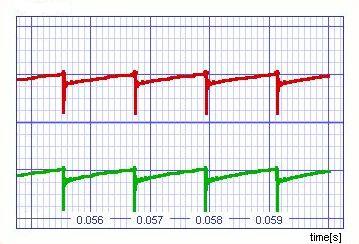
Where the red and green curves mean the voltage at R0 on receiver and at Rv on transmitter respectively (for the simulation, I've used SPICE OPUS and the capacitance distribution of transformer is replaced by the ramped constant capacitor Ct.) When the Rv on transmitter is a little smaller than R0 on receiver, the blocking oscillation frequency on transmitter is a little greater than that of receiver if they don't interfere each other. However in this case the blocking oscillation on transmitter interferes in that of receiver through antenna. As the result the frequency of receiver is "pulled in" the frequency of transmitter as shown in the following figure.
[Rv<R0]
When Rv on transmitter is decreased gradually, the frequency of transmitter goes up and that of receiver follows it linearly. But when Rv reaches a certain value, suddenly the pull-in effect disappears and the receiver has the almost independent blocking oscillation as shown in the following figure.

[Rv<<R0]
On the other side if the transmitter's frequency is smaller than receiver's one, there is no pull-in effect happened. Therefore we can use the range between the original blocking oscillation frequency and the break point frequency where the pull-in effect disappears for frequency modulation. This frequency range is cut off sharply due to on/off of pull-in effect and we can prevent the interference effectively between two adjacent channels different from usual FM which has Lorentz-type distribution as frequency band (the break point of pull-in effect depends on the strength of the RF wave from transmitter, though.) The right part of receiver in the top picture on this HTML is the simplest wave detector. You can get the intelligent signals as the voltage change at the capacitor C1.
The merit of this RF transmission system is to use MF for FM. As shown in the following figure, the blocking oscillation system has no resonant state with sine/cosine wave until 1MHz (there is a notch around 1.5MHz but it is due to the capacitance distribution of transformer and much higher than original frequency of blocking oscillation.)

Therefore the receiver using this system can avoid the interference with closing AM radio signals.
For further information about this simulation, please visit the Application Note in SPICE OPUS site.