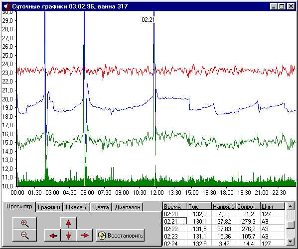
Measurement System For Pot Resistance
I use my own system for measurements of the pot resistance.
This system includes the following elements:
the pot controller (one for two pots),
controller of a potline current with the timer for
the time label generation and for synchronization and
system of network concentrators.
The pot controller is designed and implemented utilizing the
microprocessor i8085. It employes a double integration ADC
with internal optocopplers for measurements. I believe that such a
ADC is the most interesting part of my project. For the control device
of this ADC I use a timer-chip i8253.
The software of the pot controller is implemented in the Forth language.
The choice of the programming language was one of the most
important desisions taken in course of the project. The Forth language
allowed us to use a very simple and
cheap controller with 32 k ROM and 32k RAM.