Mount
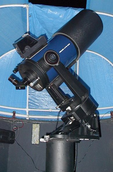
Figure 1: My LX10 Mounted in the Observatory.
Background:
Originally, when I acquired the observatory, it was to house my 8"-f/7.5 Dobsonian. The observatory worked quite well, but the scope took up a lot of space, and it was difficult to aim it near the horizon. This past spring, I purchased 8" Schmidt-Cassigrain that suited the building better. The new scope came on a sturdy tripod, which was good for portability, but did not work so well in the Observatory because of it's large footprint and because it would pick up vibrations from the floor. As a temporary measure, I drilled 2" holes in the base of the floor so that the tripod legs would reach the ground below. This helped with eliminating the induced vibrations, but every time it rained, the legs would sink a bit into the dirt, throwing off my polar alignment. It also did nothing to decrease the footprint of the scope. This led me to pursue building a proper pier to mount the scope on.
Technical Specifications:
The first step was to determine what this pier would look like. The end design was determined by the following specifications:
- It had to be easy to install and remove (in case I decide to move the observatory).
- It also had to provide a means to level it, which would make polar alignment easier, and counteract any errors in installation.
- It had to mate with my existing telescope wedge
- It had to place the scope at a comfortable position for observation
To meet the first two specifications, I borrowed a design I've seen used in mounting street lamps (you notice these things when you are stuck in traffic every day). Street lamps are often bolted to a cement base via four (or more) bolts through a base plate welded to the bottom of the post. This makes it easy to install, remove and adjust the leveling. To satisfy the third specification, I placed another metal plate on the top of the pier with a single bolt passing through the centre to mate with the wedge. Taking measurements from the tripod-mounted scope in the observatory the height of the new mount to satisfied the fourth specification. After figuring out how to put all this together, I produced a drawing and then went in search of the materials.
Procurement:
Finding and purchasing the materials was not as simple as it seemed. Will Juodvalkis & I hunted around a few scrap metal shops for the pipe and metal plates, but the prices they wanted were incredible! One place wanted $100 for 3 feet of 6"schedule 40 pipe! Fortunately, through perseverance, he managed to get me pipe for $35 ($25 + $10 to cut to size). The job then fell to me, to find two 3/8" thick metal plates that would become the base and the top. After calling around, I managed to get the remaining metal locally for only $15 (including having it cut to size). Now all I needed was a $2 bolt, some drilling and for Will to weld it up.
Construction:
After the pier was welded together and painted, it was time to install it at the observatory. The pier was designed such that I could add some fine alignment devices consistent with the existing Meade mounting holes on the wedge. Since these devices have limited movement, the mount had to be aligned as close as possible to the true north (within 5 or 10 degrees). This is an interesting task in the daytime, Polaris is not available to aid in marking out a true north south line. Normally to find a true north-south line in the daytime (since a compass would not be accurate enough), you construct a circle, set a stick in the centre and them mark off the two points where the shadow tip exactly touches the circle. Then you simply bisect these points and drawing a line from the centre to this point is your north south line. The problem with this method is it requires you to wait several hours for the sun to move enough to get both points. This is where modern technology came in. Thanks to some astronomy software, and a pdf file of a 360-degree protractor that I got off the Internet, I was able to construct a sundial good for that day. The sundial was created by plotting the sun's azimuth position as a function of time for that day. Then I mounted my sundial to the template used for holding my mounting bolts in the cement as it dried (see figure yy). By lining up the template such that the shadow fell on the correct line for the current time, I my template was instantly aligned.
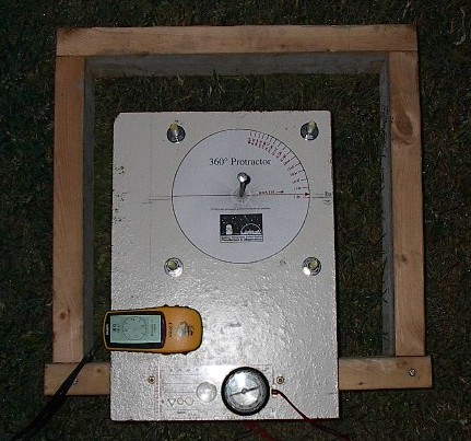
Figure 2: Pointing the mount base due North.
Installation and Commissioning:
Installation of the mount was not that straight forward. I had to separate the observatory from its base and remove the floor to pour the cement. After it hardened, I installed the pier on the mounting bolts and then replaced the floor and later the observatory. Fortunately the observatory was small enough to do this. Now I was ready for the real test - using the scope on it. It turned out that my method for aligning the pier worked quite well and it turned out that I was within a degree of the true north. Polar alignment was a breeze (relatively speaking) and now I can leave it there and not worry about it. If I were to do it all over again, the only thing I would change is to make the pipe diameter smaller as the 6” pipe was probably overkill. Now the next project is to do something about my leaking dome.
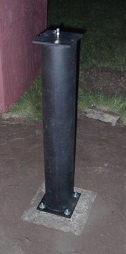
Figure 3:Mount bolted and leveled on concrete base.
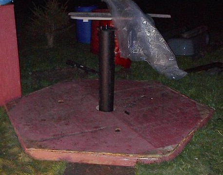
Figure 4:The mount after the Observatory base was replaced.
Assessories:
Figure 5:Altitude Fine Adjustment Control
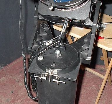
Figure 6: Azimuth Fine Adjustment Control.
The LX10 that I bought did not come with the azimuth and altitude fine adjustment controls, so I had to make up my own. Fortunately I have a relative who is a machinist and he made me up the parts I needed. See below for PDF files of the drawings I made.