

Amplifier Project Page
This page shows information and progress about my amplifier project.
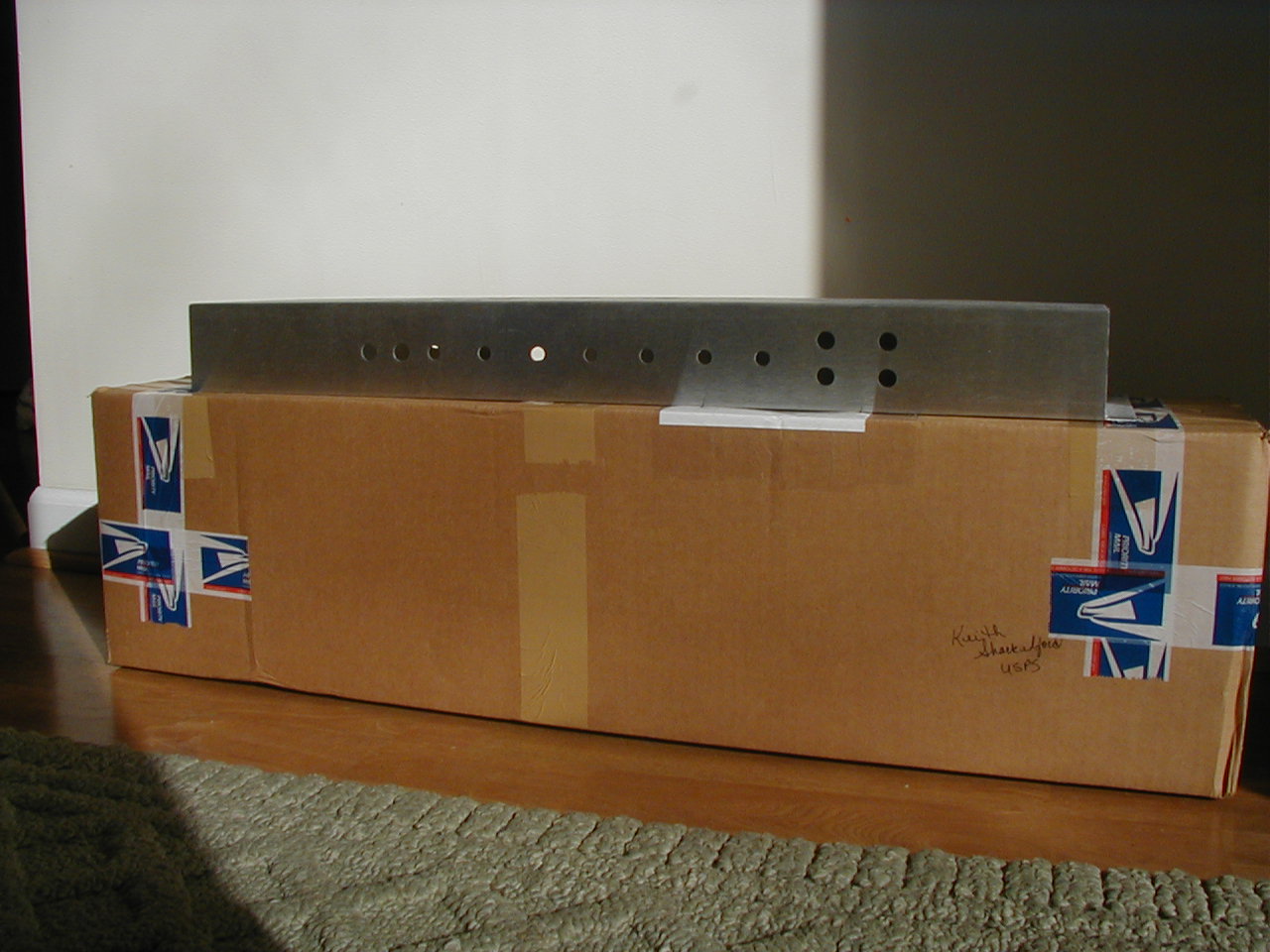
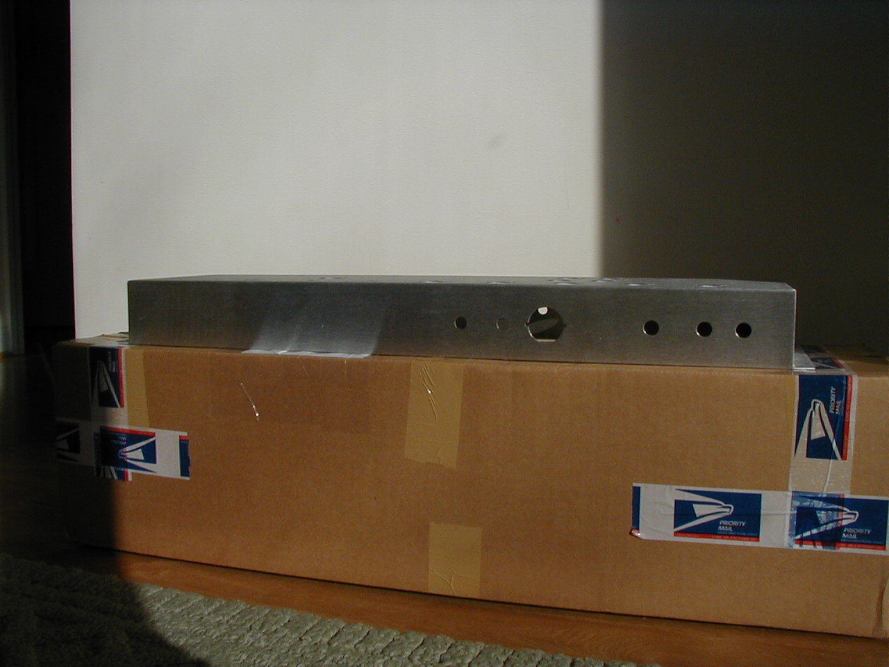
For starters....here are some pictures of the parts I have gathered so far.
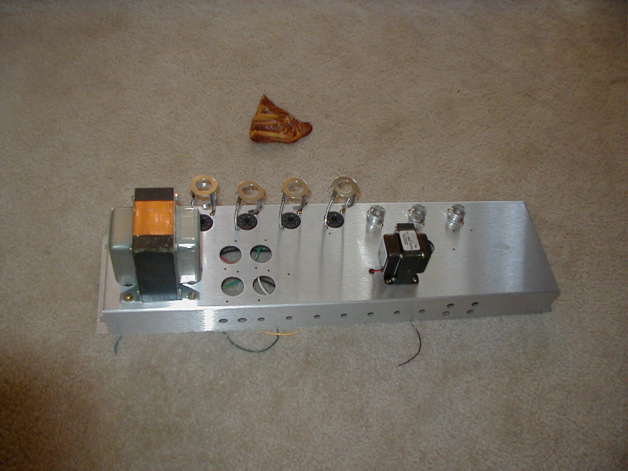
Dec. 21, 2004: The amplifier I am building is a late 1960's Marshall 100W (1959 model from '67, '68). It's a Class AB, "Push-Pull" design. This amp will not have the multiple voltage selections on it since those tranformers are more expensive and I don't plan on using this amp anywhere but the US. I layed out the Chassis in autoCad, but due to timing constraints and a generous donation (thanks dad), I found one online. The amp will have 3 12AX7 tubes in the pre-amp portion and 4 EL34 tubes in the power amp section.
![]()
Jan. 5, 2005: Today I received some more parts for the amp. In the above pictures I have mounted the tube retainers as well as the choke transformer (Mercury Magnetics 3.3H, 100 ohm, $20 @ metroamp.com).

Jan 26, 2005: If electricity is the blood of all electronics, then take a look at the heart (man I'm a nerd). The 2 new pictures above show the Heyboer Power Transformer (for now on it's the PT)that is supposed to be a replica of the '69 Marshall Drake Transformers ($120 @ metroamp.com). Transformer Specs: Primary: 120,220 and 240 taps. Secondary: 375 VAC CT @ 500mA, 94 VAC @ 60mA, 6.3 VAC CT @ 8A. I know I said earlier that I wasn't going to get a transformer with different primaries, but this one was designed for this purpose (besides, one company that I will not name was going to charge me $250 to build one like I needed). It should put about 470Vdc on the plates of the tubes. Next is the output transformer, and I'm going to take the suggestions of some more experienced folks and get good one. I'll post later which one I choose.

Jan. 28, 2005: Today my filter caps arrived. I bought 10 50x50uF @ 500V JJ's from Angela Instruments (www.angela.com) for $49. I only need 6, but most places charge $10 each. Supposedly the LCR brand is better. Being this is my first ever tube amp, I don't think I will be very dissappointed. To be honest, I'll just be happy to power it up and not have anything blow up!

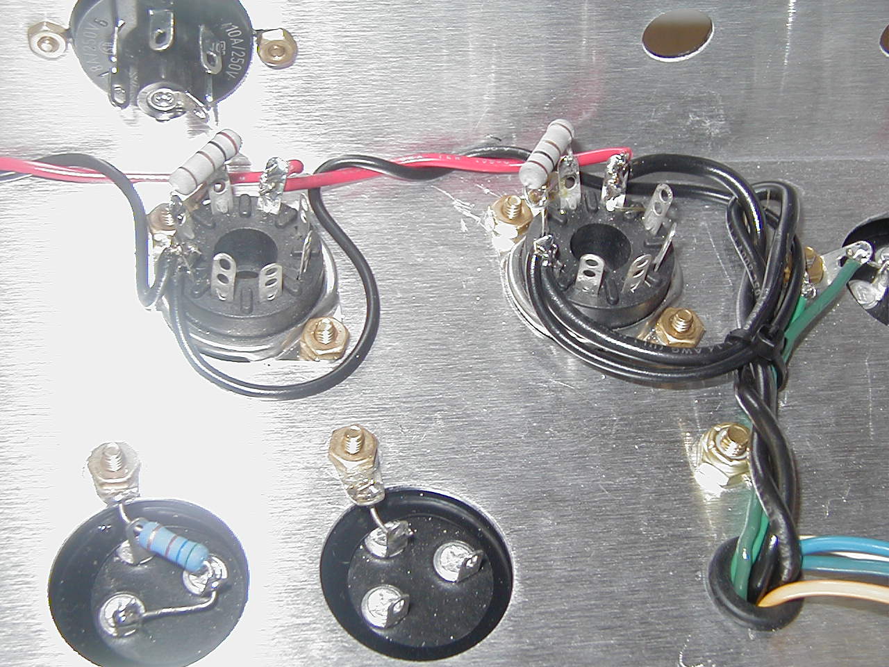
Jan. 30, 2005: Well as the Iraqi's are starting off to sleep (or party...after all it's been like 35 years) after a tough day of voting, I finished putting on my filter caps and decided to go ahead and connect the heaters for the tubes (or valves if you can say it with a british accent). Yes! Finally I have started the actual building process rather than just aquiring parts. The black and red wires (black/red to match marshall's wire color code)in the picture above are connected to the heater tap on the PT (6.3Vac @ 8A). I tried to keep the wires as short as possible and also twisted them together as tight as possible. This will help reduce that annoying 60Hz hum when the amp is powered up. In addition to the heater wires, I also mounted 1ohm resistors on the power tube sockets between the Grid and Cathode. Later when the amp needs to be biased, this will make that process easier. Hopefully by the end of February, this amp will be fully functional.

![]()
![]()
Feb. 21, 2005: I couldn't take it any longer. I have ordered an output transformer from a store on ebay, but the guy has yet to tell me it's shipped. That was 2 weeks ago and I'm rather pissed about the whole thing. So in order to continue my amp I did the only thing left to do. I began the circuit board. I originally planned to do a printed circuit board (PCB), but after looking at the cost I decided to use a point-to-point (PTP) board instead (this will also make it easier for repairs and modifications). So to start I layed out the design in autoCAD. I had a picture of a PTP board from a similar amp showing the component placement. So I layed out my board the same as the picture I had. After the autoCAD layout was finished I printed it out in a 1:1 ratio so as it would be the actual size of the board. I then taped that print out to the board to use as a drilling template. The turrets needed a 1/8" hole, and I although they are in the board now, they are not secure. I am awaiting a tool to secure them in place. Lesson Learned: Place tape strips on the board where holes will be drilled. This will keep the drill bit from tearing up the board on the top and bottom. This is why I only took pictures of the top of the board. The bottom does not look as good.
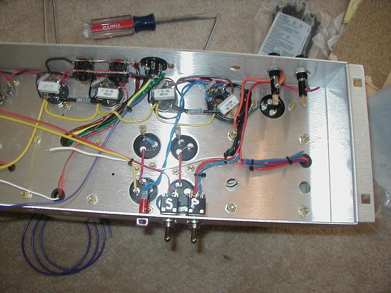
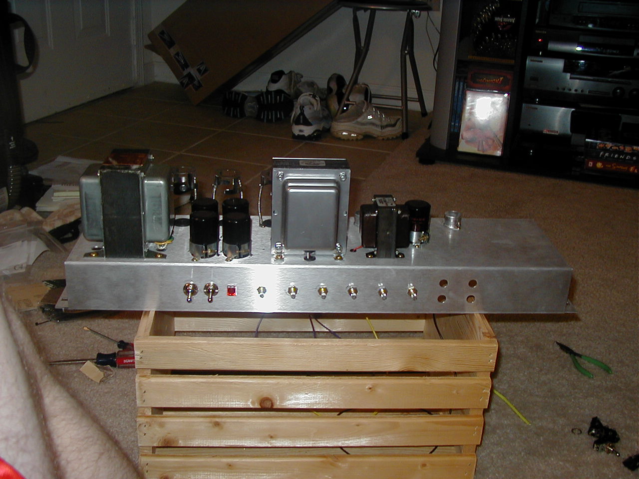
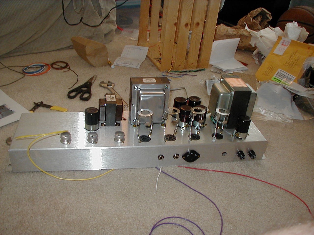
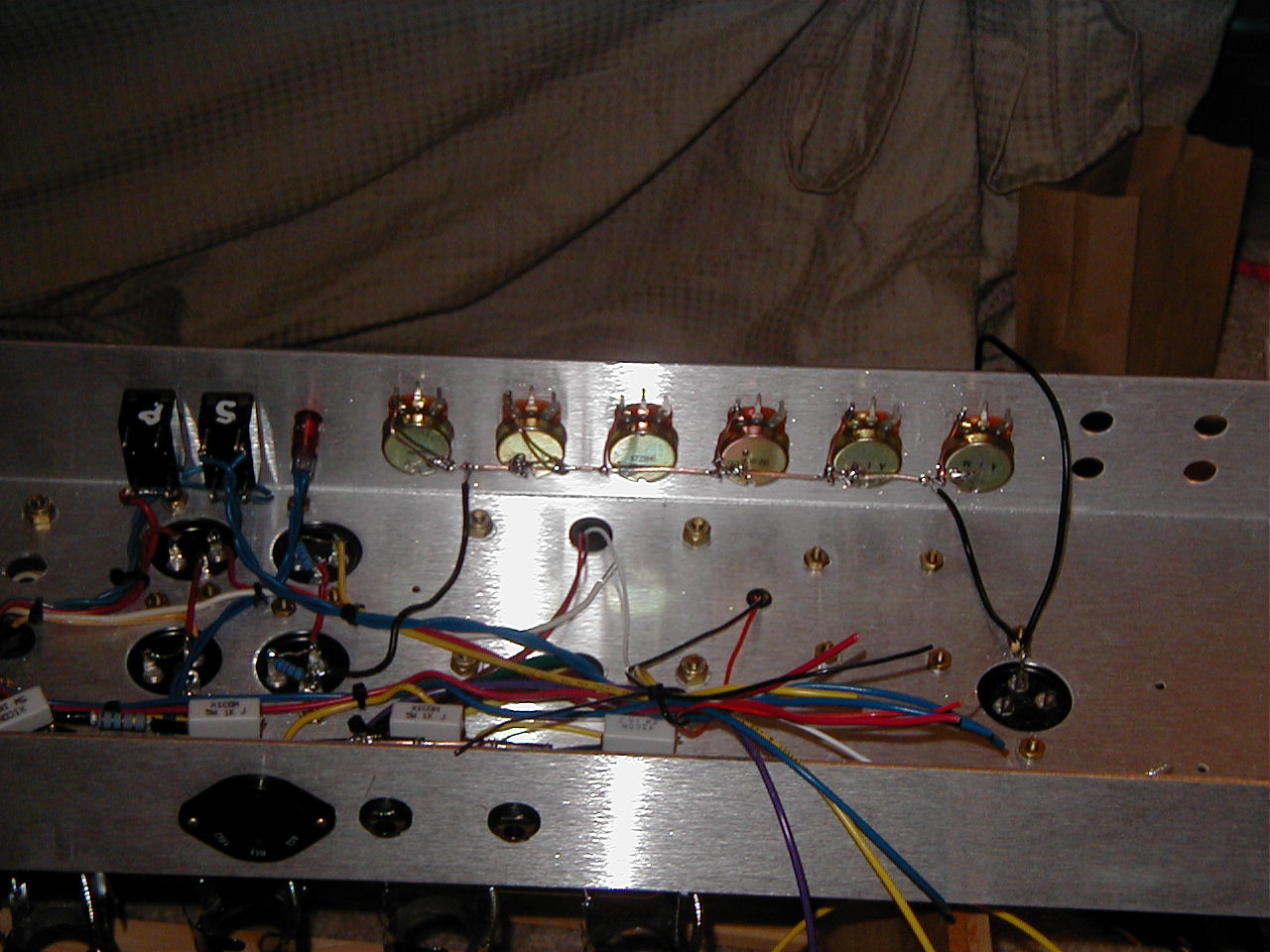
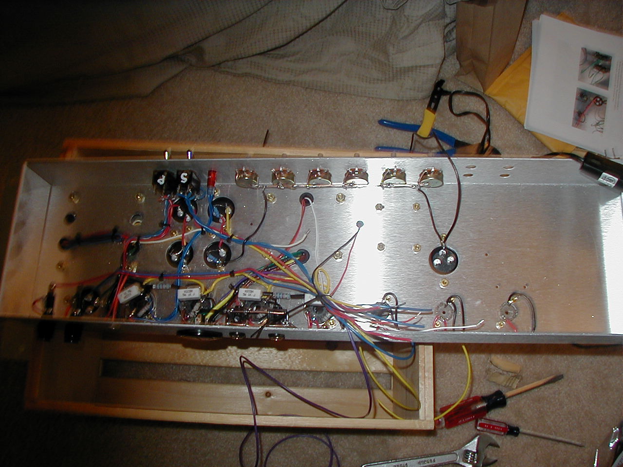
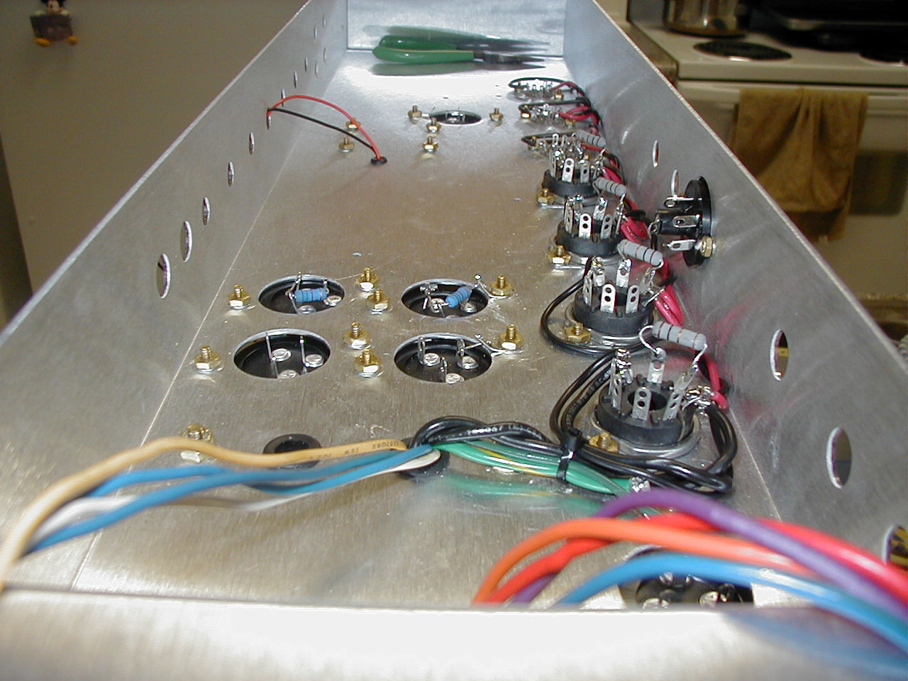
Feb. 28, 2005: Woo Hoo!!! Just as I was about to go "gangsta" on some ebay people for not delivering my output transformer, I calmed down enough to call up the credit card company and tell them to cancel the payment since the seller has not delivered (if you really want to hear the total story on this...email me). After that, I went to my reliable amp guy George Metropolous (www.metroamp.com) and ordered the Heyboer Output Transformer($120 at metroamp.com). Two hours later George calls me at home and says that he is out of the Heyboer Output Transformers and that it would be a couple of weeks. So I decided to bite the bullet and just order the really expensive Axiom Mercury Magnetics 0100 Output transformer ($225 at metroamp.com...and that's discounted!). However, as I was thinking of how to explain this purchase to my wife, George tells me that he would gladly sell me the MM (Mercury Magnetics) transformer at a bigger discount for my inconvenience. I say great and just as I was about to say what do you say to blah amount, he says just throw in an extra $30 (bringing the total to $150) and we'll call it even. I kept my excitement until the end of the phone call. It arrived on saturday and I installed it promptly. It's rotated 90 degrees from the PT to reduce noise. Today I got the output selector hooked up. I also mounted the potentiometers(3 1M Audio Taper pots for Vol1 Vol2 and Bass, 250K linear taper for Treble, a 22K linear taper for Mid, a 4.7K linear for Presence), the 1K @ 5W screen grid resistors (these are the 4 white blocks on the power tubes), the output jacks, the fuses, the indicator lamp (6.3Vac lamp), and the Power and Stand By Switches. The filter caps have been connected together as well. The excess wire is there for when the PTP board will be installed (hopefully later this week....if I'm lucky). The wire on the back of the pots is the ground buss. I had to sand off the finish of the pot case first in order to make the electrical connection between the wire and the pot case. Next I took ground terminal of the pots to this ground buss. There will be an update tomorrow night as well, so stay tuned!!!

Mar. 1, 2005: OK. This will be short and sweet. I added the input jacks and placed the PTP boad in the amp chassis today. I know I was supposed add some more yesterday, but I ran out of wire and couldn't do anything more. Hopefully at the end of the day thursday I will have the amp ready for tubes. Have a good one!


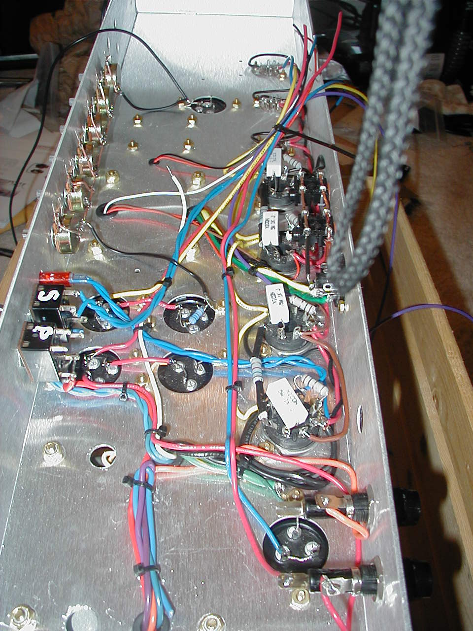
Mar. 4, 2005: Here's the majority of the wiring done in the amp. I still have to add a 100k ohm resistor across the middle pre-amp tube. Running the wires to the board took me a couple days, and a few tries but after the 3rd time I think I got it down. It was so much easier to run the wires if I connected the turret end first and then ran it through the hole in the board. Although, some wires couldn't be ran that way as the other end was already connected to something on the chassis. I also got some of the components put on in both the power section and the pre amp section. The big yellow cap is a Sozo cap (www.sozoamplification.com). I plan on using them through out the amp where I can. Check out the Sozo website for more info. Well, that is it until next week. I bought some parts from a local surplus store here in Orlando, but after checking most of the resistors and seeing how far off they are from their markings, I decided to order new ones. I also ordered a 1M ohm dual potentiometer that will be used for the post phase inverter master volume (PPIV MV mod which I'll explain later) control. Most people use one of the output jacks or one of the input jacks for this, but I'm going to just drill a hole in the rear of the chassis for it. It's not going to ruin any garuntees or vintage value so what the heck. March 11th is D-Day! That's my goal for the amp being powered up for the first time. However, I don't have a speaker cab to plug into. However hopefully through some friends we can find on to test with. Have a good weekend!!!!!


Mar. 11, 2005: Power Up Day! Ok, so that's a gay title. Anyway........
p align="Left">Today I finished the PTP board and installed the AC chord. I plugged it in and with absolutely no fear turned on the power switch (the safety glasses were for OSHA reasons). I took a couple voltage readings on the bias tap (measured 101Vac), the heaters (measured 3.00Vac), and the wall voltage (measured 124Vac). Next I took a voltage reading for the power tube bias voltage and it measured -2.2Vdc (should be approx. -40Vdc). I powered down the amp and did some continuity checks to make sure I was not bleeding and voltage to ground. The problem was that I had the two 10uF bias capacitors inserted wrong (luckily either way it went the caps would not have exploded). So I turned those around and the voltage measured -30Vdc. When changing the bias pot, the voltage ranged from -30Vdc to -40Vdc. I was expecting it to range from -30Vdc to -50Vdc. I might have to change out one of the bias resistors. Once that was fixed, I decided to turn on the Standby switch. The pics were taken tonight and I tried to capture the voltage readings in the pics. My B+ supply voltage was reading 530Vdc earlier today, but now it's down to 513Vdc (I was expecting approx. 490Vdc) on the power tubes. On the pre-amp tubes I was measuring 463Vdc earlier today, and now it's down to 448Vdc. I was told that without the tubes, the voltages will be about 20% higher. Makes sense in that no load is on the PT. Tomorrow I will change out the 47k ohm bias resistor to see if I can get a bigger range in my bias voltage. I am also going to check out some tubes. I'm thinking of using Electro Harmonix 12AX7s and Electro Harmonix EL34s. This is my first tube amp ever, so I have no idea which tubes are best. I just know that these are no the cheapest nor are they the most expensive.

p align="Left">Right now the amp is just like the original schematic I found. I have made some slight changes in capacitor values and resistor values, but nothing major. For those who take notes like this, I am using a split cathode on V1 (1st pre-amp tube). The bright channel (channel 2) has a 0.0022uF coupling cap between V1 and the bright channel volume pot. I also used a 33k slope resistor, for more of a "super lead" sound rather than a "super bass." I also used a 100k ohm feedback resistor connected to the 8ohm tap. I used 0.1uF caps in the phase inverter. I mostly used 1W metal film resistors (Vishays), except for a few places that I forgot to order metal film for and I therefore went to Radio Shack and got carbon film. Some resistors I couldn't get in the Vishay 1W (unless I wanted 1000 of them), so I went for other sizes like 2W and 3W (those really small 100k's are 1W metal film flame resistant....it's all they had in the minimum orders of 1).

p align="Left">I still have yet to add the master volume. I will be using a Post Phase Inverter Master Volume. This will allow the phase inverter tube to act as a pre-amp tube as well in that it can be driven to saturation and therefore adding to the distortion (Rock n Roll!!!!). So I will be able to run the normal volume and bright volume at full and not kill myself at the same time. This will be done using a 1M ohm dual ganged potentiometer. Out of the phase inverter are 2 signal, each 180 degrees out of phase with each other. Each of these signal will be connected to one side of the dual ganged pot. The only thing I am unsure of is how this will affect the frequency response of the amp. Some people use an attenuator between the amp and speaker cab for this. However, those cost about $300. The big sale there is that your amp stays stock and is not modified in any way (some say the attenuators sound better than the MV mods, but I don't know....haven't used either of them before). For an overdrive sound, I will need to be able to turn the normal and bright volumes at or near full (11 maybe?). The PPIV MV will keep the power tubes from being overdriven (after all, I'm not Eddie and can't afford new tubes every week).