A TRANSIENT ANALYSIS OF AN IMPEDANCE TRANSFORMING DEVICE
by Robert Lay
W9DMK
10 October 1998
The Quarter Wave Transformer
Reference (a): "Transformation Calculus and Electrical Transients", Stanford Goldman.
OBJECTIVE:
To analyze the behavior of the system under startup transient conditions with a view towards understanding the nature of the impedance transformation that takes place, at Point X, in a quarter wave line (Line 2) during the transient conditions.
SYSTEM DESCRIPTION:

Generator: 50 ohm Generator (Develops 1 watt into matched load)
Line 1: 50 ohm Line, Zo = Ro = 50 (lossless, any length)
Point X: Transition from Line 1 to Line 2
Line 2: 150 ohm Line, Zo = Ro = 150 (lossless, electrical quarter wave)
Termination: 450 ohm load
CONSERVATION OF ENERGY:
Given the length of Line 1 and the Frequency, we will also be able to perform a conservation of energy test for the system consisting of Lines 1 and 2 and the termination. For purposes of this example, we arbitrarily assign Line 1 to be 30 meters long and we assume a Frequency of 7.5 MHz. (Line 2 thereby becomes 10 meters long as a direct consequence of the requirement to be 1/4 wavelength). The conservation of energy computations will follow the description of the various transient events.
EVENT 1:
At time t=0, the Generator originates a sinusoidal wave at the frequency for which Line 2 is one quarter wavelength.
EVENT 2:
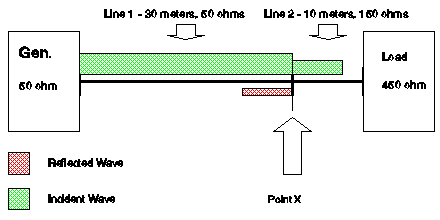
The sine wave arrives at Point X and is partially reflected by the impedance discontinuity that exists at that point (see Note 3). The impedance discontinuity is defined by the reflection coefficient, which is of the form N = (Ro -Rt)/(Ro+Rt). Line 1 has a characteristic impedance of 50 ohms, and at this particular event, Point X presents an impedance of 150 ohms (see Note 3), and as a consequence of that impedance mismatch, the voltage reflection coefficient is 0.5. (See Rule III)
In Line 1 a reflected wave now originates in the region just to the left of Point X and coexists with the incident wave in that region. In that region where both waves exist, the incident wave stands at a level of 1.0 watts and the reflected wave is at 0.25 watts. This satisfies all constraints relative to the SWR of 3:1, the reflection coefficient of 0.5 and the net energy flow into Line 2 of .75 watts. In Line 2, an incident wave originates at a level of 0.75 watts. (See Rule III)
The following diagram illustrates the conditions that exist after Event 2 and prior to Event 3:
EVENT 3:
At Event 2 plus 90 electrical degrees (see Note 1 below) the wave traveling on Line 2 arrives at the 450 ohm termination and is partially reflected with a reflection coefficient N = (Ro-Rt)/(Ro+Rt). At this event the reflection coefficient is based on a Line 2 characteristic impedance of 150 ohms and a termination resistance of 450 ohms, giving a reflection coefficient of 0.5. As a result of the partial reflection occurring at the 450 ohm Termination, there will again be a distribution of the power with 75% being dissipated in the 450 ohm termination and 25% being reflected. In the region immediately to the left of the 450 ohm termination a reflected wave originates toward Point X. In the region where both the incident wave and the reflected wave coexist, the incident energy flow is .75 watts and the reflected wave is at .1875 watts. As in Line 1 above, all constraints relative to an SWR of 3:1 and a reflection coefficient of 0.5 are met by these power levels, including a net energy flow of .5625 watt into the 450 ohm load.
The following diagram illustrates the conditions that exist after Event 3 and prior to Event 4:
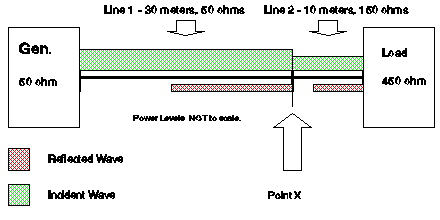
In Line 1, the reflected wave is still traveling from Point X towards the generator and will not reach the generator until Event 5.
We should now pause to look more closely at the coexistence of the reflecting wave and the incident wave in Line 2. The reflected energy flow at each point subtracted from the incident energy flow at each point equals the energy flow into that point from the left (conservation of energy principle - see Notes 3 and 5). The consequences of this are that at each point along Line 2, the impedance seen at that point is completely consistent with the voltage and current phasor sums of all traveling waves at that point (see Notes 2 and 4). Additional analysis of these power levels, given that we know the characteristic impedance of the line, also allows us to calculate the impedance seen at any point on Line 2. The impedance calculated is the "impedance seen at a point" - a function of the characteristics of the line, the distance to the termination and the impedance of the termination. (See Rule III)
Contrast this with the advance of an incident wave which is traveling towards an impedance discontinuity but has not yet reached it. In that case, the traveling wave sees only the characteristic impedance of the line, which appears to be of infinite length or terminated in its characteristic impedance. (See Rules I & II)
In Line 1, the incident and reflected power levels are dependent upon whether we are looking at a portion of Line 1 in which there is a reflected wave, or not. Immediately to the left of Point X there is a reflected wave traveling toward the generator. It will not arrive at the generator until Event 5. Meanwhile, the generator continues to deliver 1.0 watts to Line 1. The reason that the power entering Line 1 is still 1.0 watts is that the generator does not see an SWR that would cause a power reduction - the reflection from Point X has not yet reached the generator. At Event 5, that situation will change as the reflected energy from Point X arrives at the generator.
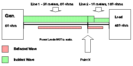
EVENT 4:
At Event 3 plus 90 electrical degrees, the reflected wave traveling to the left on Line 2 arrives at Point X. At this same instant the reflected energy on Line 1 is traveling towards the generator but is still 33 nanoseconds away.
The impedance seen looking to the right from Point X is now seen to have changed by virtue of the arrival of the reflected wave at that point. The impedance at Point X is no longer 150 ohms. The new impedance at that point can be determined in either of two ways - a) by combining the incident and reflected wave phasors at any point of interest, or b) by using a Smith Chart or an impedance equation based on length of line, terminating impedance and characteristic impedance.
The energy flow from Line 1, passing into Line 2, is 0.75 watts. The reflected voltage wave in Line 2 has a magnitude of 5.35 volts. The reflected current wave is .035 amps. Note that this satisfies the constraint that the Voltage to Current ratio in Line 2 be 150 ohms for the reflected wave. Also for that same incident power level, the incident voltage wave in Line 2 has a magnitude of 10.67 volts, and the incident current wave in Line 2 is .071 amps. This satisfies the constraint that the incident voltage/current ratio in Line 2 be 150 ohms. The incident and reflected phasors combine to produce a (summed voltages/summed currents) ratio representing the impedance at that point, provided that the relative phase angles of each wave are properly accounted for (see Note 4 and Rules I through IV)
We should now pause to consider the phase angles for the phasors on Line 2, which are a function of the total distance traveled in electrical degrees. At any point to the right of the leading edge of the reflected wave, the phase angle of the reflected wave and the phase angle of the incident wave will be a function of the distances traveled to that point. The phase difference is a minimum of 0 degrees (directly at the 450 ohm Termination) and is a maximum of 180 degrees (immediately to the right of Point X). There is one additional consideration, and that is that when a line is terminated with an impedance greater than its characteristic impedance, the reflected current wave is given a 180 degree phase shift at the point of reflection. Conversely, when the terminating impedance is less than the characteristic impedance, the reflected voltage wave shifts 180 degrees at the point of reflection (See Rule VI). Remembering that Line 2 is a 150 ohm line terminated with a 450 ohm Termination, it is readily determined that immediately to the right of Point X, the incident and reflected voltages sum to (10.67- 5.335) volts, while the incident and reflected currents sum to (.071 + .035)amps, indicating an impedance of 50 ohms. Note that Line 1 is now terminated in its characteristic impedance (See Rule III). The consequences of this are dramatic.
With Event 4, the reflected wave in Line 1 might be expected to continue traveling to the left of Point X and in the direction of the generator. Were it not for a dramatic change in conditions that occurs precisely at the moment the reflected wave arrives at Point X, the reflection in Line 1 at Point X might continue indefinitely. However, the reflection that was caused by the mismatch at Point X ceases with Event 4. That reflection existed only for the period of time from Event 1 until Event 4, because during that period and that period only, the impedance seen at Point X was not equal to the characteristic impedance of Line 1. With Event 4 the impedance seen at Point X instantaneously changes with the arrival of the reflected wave from 150 ohms to 50 ohms, and the reflection of power from Point X ceases at that instant. (There will be a small energy flow from Line 2 that passes at 75% level from Line 2 into Line 1 as a result of reflections from the 450 load, but that will eventually die out as steady state is eventually reached. Steady state in Line 2 will have an incident power of 1 1/3 watts and a reflected power level of 1/3 watts for a net flow of 1 watt to the load.)
The following diagram illustrates the conditions that exist after Event 4:
Beginning with Event 4, the trailing edge of the original reflected wave in Line 1, will continue toward the generator and will eventually disappear entirely. Note that the duration or length of the reflected wave in Line 1 is equal to twice the length of Line 2.
As will be seen in the Conservation of Energy Test, a portion of the reflected wave in Line 2 will continue past Point X, (75% of the value of the reflected wave in Line 2), until steady state conditions are reached. See Note 6 for additional notes on the reflected wave in Line 2 subsequent to Events 4 and 5.
EVENT 5:
The reflected energy from Point X begins arriving at the generator. At all points on Line 1 where the reflected energy wave coexists with the incident wave, there will be a different power level for the incident wave and an impedance seen at those points which is, in general, not the characteristic impedance of the line. The incident power level is 1.0 watts, the reflected power level is .25 watts, and the impedance will be as determined by the sums of the voltage and current phasors. There is another, easier way to find the steady state impedance. Since the length of Line 1 is 30 meters, or 3/4 wavelength at the frequency we have picked for our Conservation of Energy Test, it presents the same impedance as would a one quarter wavelength line - namely, 16.666 ohms. That is the impedance that would be seen from the generator if Line 1 were terminated in 150 ohms, steady state. However, using the traveling waves with their phase angles, consider that the arriving reflected voltage wave has traveled 60 meters round trip and it has undergone a 0 degree additional phase shift at Point X (See Rule VI). Therefore, the reflected voltage wave arriving at the generator has an angle of 540 degrees, which is the same as 180 degrees insofar as sin and cos functions are concerned, and is also equivalent to being multiplied by (-1). The reflected current wave has traveled the same distance and has an additional 180 degree phase shift that was applied at the reflection point, Point X (See Rule VI). Therefore, its phase angle is 720 degrees (the same as zero degrees). The reflected wave is 0.25 watts traveling in a 50 ohm line and therefore has a voltage/current ratio of 3.5v/.07a = 50 ohms, while the incident wave at a power level of 1.0 watts is 7.07v/.141a. Consequently, the sum of the incident and reflected voltages produces a voltage/current ratio of (7.071 - 3.536)volts/(.141 + .071)amps = 16.66 ohms. Q.e.d. However, these calculations represent a condition where there is reflected energy on Line 1, and that condition will exist only as long as the transient traveling wave energy is arriving at the generator (that is until t=266 nanoseconds). That anomoly persists until the reflection disappears, at which time an incident wave of 1.0 watts will be the only energy flow on Line 1, and the impedance seen by the generator will again be 50 ohms.
A Dilemma Has Arisen -
As soon as this traveling wave of reflected energy arrives at the generator, the generator sees a mismatched load impedance, and a simple generator would not be able to deliver the nominal 1.0 watts into the line under those conditions. Unfortunately, there is no closed form solution for this situation. In order to avoid this dilemma, we must terminate the accounting process for the Conservation of Energy Test at Event 5.
STEADY STATE:
The steady state condition has a 1 watt net power level throughout the systemand an SWR of 3:1 in Line 2. Only in Line 2 is there a reflected wave.
CONSERVATION OF ENERGY TEST FOR INTERVALS FROM EVENT 1 TO EVENT 5:
Units of time are nanoseconds and units of energy are nanojoules
Event 2 is at t=100.
Event 3 is at Event 2 + 33 1/3, or t=133 1/3
Event 4 is at Event 3 + 33 1/3, or at t=166 2/3
Event 5 is at Event 4 + 33 1/3, or at t=200
The events define four intervals as follows:
Int(a)= 100,
Int(b) = Int(c) = Int (d) = 33 1/3
Total energy (watts * time) supplied to the line by the generator is as follows:
1.0 watts * (Int(a) + Int(b) + Int(c) + Int(d)) = 200, total.
Total energy supplied to the 450 ohm termination is as follows:
(0 * Int(a)) + (0 * Int(b)) + (.5625 * Int(c)) + (.5625 * Int(d)) = 37.5
Total energy stored in the lines at the conclusion of events:
Line 1:
(1.0 * Int(a)) + (.25 * (Int(b) + Int(c)) + (.1875 * 75% * Int(d)) = 121.35. Note that this includes reflected energy originating as a reflection from the 450 ohm load and passing through (at 75%) Point X in a right to left direction. The 75% is due to the fact that Point X appears as a 50 ohm termination for a wave traveling on a 150 ohm line).
Line 2:
(0 * Int(a) + (1.0 * Int(b)) + (.1875 * Int(c)) + (.1875 * 25% * Int(d)) = 41.15. Note that this includes 25% reflection at Point X of the reflected wave originating at the 450 ohm load. The 25% is due to the fact that Point X appears as a 50 ohm termination for a wave traveling on a 150 ohm line.)
Total energy stored in the lines = 121.35 + 41.15 = 162.5
Total energy input to the system (200) = total energy dissipated (37.5) + total energy stored in lines (162.5). Q.e.d.
A few words of explanation of the Conservation of Energy Test are in order. The Conservation of Energy Test was originally intended to be a very simple corroboration by independent calculations. The dilemma regarding the source generator made that impossible, since we were forced to end the energy accounting at Event 5 instead of waiting until a steady state condition has been reached. Another point of confusion is my choice of computing energy as the product of power and time. This is a convenient but inappropriate computation for energy stored in a transmission line in that the intervals should be converted to distances and the power levels should be converted to joules per unit of distance. The correct answers in nanojoules are obtained using the method shown, but it does omit certain steps that should be obvious.
At first glance, it may not seem appropriate to consider energies in the lines that are traveling to the right (incident) and energies traveling to the left (reflected) as simply adding together. When we were discussing "net energy flow" we treated energy flows in opposite directions as cancelling each other out. That was an appropriate view for purposes of computing instantaneous net flow, because it is appropriate to prohibit an energy source or sink at a point on a transmission line (See Rule IV). The rationale' for summing all energies stored in a transmission line irrespective of the direction of flow in the Conservation of Energy Test is based on these points:
First, the incident and reflected energies traveling in the line each represent a stored energy over a finite length of line - not a point.
Second, the summation of stored energy is an integration of "an energy (joules) per unit distance" over a length of line at a specific instant of time.
An analogous situation is seen in a river that has counterflows along the banks. Measurements of water velocity at various points across the breadth of the river have to be summed with regard to the magnitude and direction of flow indicated at each measurement point in order to determine the net flow of the river. But at any given moment in time, the total volume of water in a specified length of the river must be computed by integrating the volume of water over that section of the river without regard to the direction of flow at any point.
Note 1: TIME, VELOCITY AND LINE LENGTH
The relationships between velocity, time and electrical degrees for a lossless line is w/b = c where w is radian frequency (usually assigned the Greek letter Omega), b is the phase shift constant for the line in radians per unit length of line (usually assigned the Greek letter Beta), and c is the velocity of propagation, roughly 300,000,000 meters per second. For example, a line of approximately 10 meters length at 7.5 MHz (47,000,000 radians per second) has an electrical length of 1.57 radians, or 90 electrical degrees, and the signal travels this distance in 33 1/3 nanoseconds.
Note 2: IMPEDANCE SEEN AT A POINT ON THE LINE
Perhaps the most striking characteristic of transmission lines is the concept of impedance at a point on the line being a function of the distance to and the value of the terminating impedance - all of which is a direct result of the fact that the electrical parameters of a transmission line are distributed rather than lumped, and the fact that the velocity of signal propagation on transmission lines is finite. The impedance at a point on a transmission line is defined specific to a direction. The usual convention is to define it in the direction of net energy flow. The line is "virtually" cut at the point of interest and the impedance is defined as that impedance which would be seen looking into the line from the point of the virtual cut. The impedance is determined not by traveling waves but rather by the line characteristics and the terminating load in the direction of interest. A Smith Chart may be used as a quick display of impedance values. The sum of all traveling waves, incident and reflected, at the point of interest will define a voltage/current ratio at a point which will be consistent with the impedance at that point as defined above. The important significance of that is that actual measurements of voltages and currents on real transmission lines, whether using voltmeters, ammeters or oscilloscopes, will correlate or agree with this "impedance seen at a point". Contrast this with the concept of the impedance seen by a single traveling wave as described in Note 3, below.
Note 3: ENERGY FLOW AND IMPEDANCE SEEN BY INDIVIDUAL TRAVELING WAVES
The energy in a traveling wave arriving at an impedance discontinuity will be partially passed through and partially reflected as a function of the reflection coefficient. Both an incident and a reflected wave are created at an impedance discontinuity. The voltage/current relationship of an individual traveling wave will automatically conform to the characteristic impedance of the line at every point. Note that we are referring to the characteristic impedance of the line, not the "impedance seen at a point" discussed in Note 2, above. In other words, for a given flow rate of energy entering a line, the voltage and current are determined solely by energy flow rate (power) and the characteristic impedance of the line at that point. It should also be noted that while the individual traveling wave conforms to the characteristic impedance of the line in which it travels, it is also quite oblivious to the termination or source impedances. Contrast this concept with Note 2, above.
Note 4: PHASORS
In this paper we are not interested in the instantaneous value of a sine wave but rather in its phasor representation. For example, in the function of time, f(t) = A * cos(wt + theta), the sine wave has a radian frequency of w = 2 * Pi * F and a relative phase angle, theta, relative to some appropriate reference. To the extent that all sinusoidal functions in the system are at the same radian frequency, and the sinusoidal functions are all phase related to the same reference for determining relative phase angle, the phasor representations can be manipulated as complex quantities either in Cartesian or Polar coordinates.
Note 5: TRANSIENT BEHAVIOR OF TRAVELING WAVES AND ENERGY FLOW BALANCE
It has been shown in Reference (a) that signals introduced to a lossless transmission line, terminated in non-reactive source and load, will propagate without change in waveform and with a velocity of 1/(sqrt(LC)). That is, the voltage at an arbitrary distance x along the direction of propagation is exactly similar to the voltage at x=0, with no attenuation or change of wave form, except that there is a time lag in the amount x * sqrt(LC). In this paper we assume that in order to properly assess the effects of waves traveling on the line in question, it is only necessary to account for those waves that are physically present at the point of interest. For example, a wave-train that is traveling to or away from the point of interest is of no concern if it is completely past the point or has not yet arrived at the point of interest. This assumption is of particular importance when summing the phasor representations of all waves present in order to calculate the impedance at a point. For purposes of determining the direction of energy flows, the incident wave is considered by definition to be a positive energy flow, while the reflected wave is by definition a negative energy flow. In a Conservation of Energy Test calculation, however, the total energy is an integration of energy per unit length at an instant in time, irrespective of direction of flow. That is, the energies present in waves traveling in opposing directions do not subtract from each other when determining the total energy stored in a finite length of line at a given instant.
Note 6: ADDITION NOTES ON DISAPPEARING REFLECTIONS
The reflected wave in Line 2 after Event 5 does continue to flow through Point X and into Line 1 as part of the transient phase. However, it eventually disappears as the transient phase completes (beyond Event 5). That is, the reflections to the left of Point X eventually die out and in the steady state condition do not exist.
DEFINITIONS:
Impedance Discontinuity - a junction or transition point where lines join. The discontinuity is trivial if the two lines have the same Zo.
Combination of Standing Waves - the phasor sum of incident and reflected waves at a point on a line.
Energy Flow Balance - The energy flows into ( + ) and out of ( - ) a point or defined region not containing an energy source or sink must always sum to zero. Contrast this with a Conservation of Energy calculation wherein the energies present in a finite system are all added together without regard to an "direction of flow" (See also Rule IV).
Reflected Impedance - the impedance seen at a point on a line as determined by the "Combined" voltages and the "Combined" currents present at that point (the incident and reflected waves).
RULES (For either transient or Steady State Conditions):
Rule I. The Zo of the line determines the voltage/current ratio for the traveling wave (of either direction), i.e., E = I * Zo.
Rule II. The Zo of the line determines the voltage and the current for a given energy flow in a traveling wave (of either direction). I.e., P = (E^2)/Zo or (I^2) * R [This does not attempt to define which is the "cause" and which is the "effect" - energy flow (power), or voltage or current.]
Rule III. The Reflection coefficient (Rho) is determined solely by the impedances (Zo - Zx)/(Zo + Zx), where Zx is the "reflected" or "transformed" impedance seen at the Impedance Discontinuity. The "reflected" or "transformed" impedance will be the Zo of the receiving line when there is no "reflected" energy arriving at the junction. In general, this impedance is defined by the combined incident and reflected waves.
Rule IV. The sum of the energy flows into a point must equal the sum of the energy flows exiting that point. (Algebraic sum of the energy flows is zero). For example, if the incident power is 1 watt and the reflected power is 1/4 watt, then there will be 3/4 watt continuing through the junction. This rule is based on the constraint of no energy source or energy sink at the point.
Rule V. If the impedance discontinuity or transition is the connection of a line to a "load", then that "load" will follow the same rules as would a transmission line insofar as reflection coefficient, energy flow balance, etc.
Rule VI. 180 degree phase reversals occur in the reflected wave at an impedance discontinuity in accordance with the following criteria:
Current is reversed when Zx > Zo and Voltage is reversed when Zx < Zo.