PRACTICAL APPLICATION OF BROKEN BAG DETECTOR TECHNOLOGY

FOR COMPLIANCE, OPERATION & MAINTENANCE UNDER the STEEL MAKING EAF -
NSPS and the IRON & STEEL FOUNDRY NESHAP ©2004
authors:
JOSEPH C. WESSELMAN, CORPORATE ENVIRONMENTAL DIRECTOR IPSCO ENTERPRISES INC.
and
CHARLES W. ASKINS, P.E., CHMM, CHCM, PRESIDENT AG ENVIRONMENTAL SERVICES, INC.

Key Words: Foundry NESHAP, EAF NSPS, Broken Bag Detector, Triboelectric BBD, BBD Technology, Foundry MACT
Introduction

This paper will discuss the practical installation of Broken Bag Detection (BBD) technology for cost effective compliance with the Electric Arc Furnace (EAF) New Source Performance Standard (NSPS) and the Iron & Steel Foundry National Emission Standard for Hazardous Air Pollutants (NESHAP) applying a Maximum Achievable Control Technology (MACT) standard. A review of the current status of these rule revisions, and their application to the respective EAF and melting furnaces that will be subject to the standards is discussed in this paper.

Regulatory Background

On October 16, 2002 USEPA published a proposal to modify the New Source Performance Standards (NSPS) for Electric Arc Furnaces to allow for the use of bag leak detection systems to be used in the place of continuous opacity monitors on EAF baghouses with single stacks. While USEPA has never finalized this rule, they have made other proposals to utilize bag leak detection systems for monitoring baghouse performance. On April 22, 2004 USEPA published a final rule promulgating a National Emission Standard for Hazardous Air Pollutants (NESHAP) for Iron and Steel Foundries. While this rule, commonly known as the Foundry MACT, addresses a number of hazardous air pollutants from several different operating practices, this paper will focus only on the proposal to include bag leak detection for monitoring the filter fabric baghouses at these operations.

Iron and Steel Foundries utilize filter fabric baghouses for controlling the particulate laden fume generated during melting operations. This particulate is composed primarily of iron oxides, however it does contain some metal oxides that are considered hazardous air pollutants, depending on the nature of the scrap charged to the furnace. In the Final NESHAP Rule for Iron and Steel Foundries USEPA states their conclusion that controlling particulate matter (PM) is the most effective way of controlling metal HAPs, with the possible exception of mercury, and that it is appropriate to use PM as a surrogate for metal HAPs. While steel making Electric Arc Furnaces are not subject to MACT requirements, this industry has a long history of installing and updating large filter fabric baghouses for controlling the PM generated by the scrap melting process. This has resulted in an Opacity Limit of 3% from the baghouses, one of the most stringent opacity standards applied to any industrial operation.

In the authors' opinion, it is clear that a properly designed and maintained baghouse is an extremely efficient method to control PM from the melting operations in both of these industry sectors. It also appears that USEPA feels that utilizing bag leak detection systems is the most effective method to provide continuous compliance monitoring for these baghouses.

This paper will compare and contrast the bag leak detection system requirements contained in the October 16, 2002 Proposed NSPS rule, and the April 22, 2004 final NESHAP rule. In addition the authors will discuss real world experience with leak detection systems at two Electric Arc Furnace facilities operated by IPSCO Steel in the United States.

Regulatory Requirements

It is important to note at the outset that these two rules are very different in their scope. The proposed EAF NSPS rule is very narrow in scope, addressing only the use of broken bag detectors as an alternative to continuous opacity monitors and only on single stack baghouses. While the Foundry NESHAP rule is broad in scope covering a variety of pollutants at multiple emission sources located at an iron and steel foundry. For the purposes of this discussion only the requirement for use of broken bag detectors contained in the foundry NESHAP will be evaluated and compared to the proposed EAF NSPS rule.

Both the proposed NSPS rule, and the final NESHAP rule have three basic requirements related to the installation and use of a broken bag detection system. They are: (1) a minimum set of system design requirements; (2) a requirement to develop an operation and maintenance plan for the broken bag detection system; and (3) corrective action requirements to respond to alarms generated by the broken bag detector. The similarity between the basic requirements outlined in both rules provides a good indication of what USEPA believes is necessary to provide continuous compliance monitoring for baghouses used in the metals industry.

System Design Requirements

In defining a broken bag detection system USEPA recognizes that there are several different technologies that could be used. They include but are not necessarily limited to systems that operate based on triboelectric effect, electrodynamic effect, light scatter, or light transmittance. Neither rule dictates which system to use but both rules set as a minimum, the requirement to be capable of continuously monitoring the relative particulate matter loadings in the exhaust from baghouses. The intent is to be capable of measuring changes in the relative particulate loadings to identify damaged bags or other types of upset conditions that occur in a baghouse. The following points are some of the basic design criteria that are listed in both the proposed NSPS rule and the final NESHAP rule:

1. The system must be certified by the manufacturer to be capable of detecting particulate matter concentrations of 10 milligrams per cubic meter (0.0044 grains per actual cubic foot) or less.

2. The system must provide an output of the relative particulate loading, and this output information must be continuously recorded by electronic or other means.

3. The system must be equipped with an alarm system to detect increases in the relative particulate loadings above a set point. This set point is to be established in accordance with the sites operation and maintenance plan. Additionally the alarm must be located so that it is audible by the appropriate plant personnel

4. When broken bag detection systems are installed on either positive or negative pressure baghouses with a stack, the broken bag detector system sensor must be located downstream of the baghouse and upstream of any wet scrubber.

5. When multiple detectors are required, the system instrumentation and alarms maybe shared among detectors.

Operation & Maintenance Plan Contents

Both rules include the requirement to develop a site-specific monitoring plan. These plans are subject to review and approval by the Administrator or the delegated regulatory authority. Both rules also include a reference to a USEPA Guidance Document "Filter Fabric Bag Leak Detection Guidance" (EPA-454/R-98-015) for assistance in development of the site specific monitoring plan, however, the rules also require that the plans at a minimum address the following

1. Details on the installation of the broken bag detection system.

2. A description of the operation of the broken bag detection system.

3. A description of the maintenance procedures, including routine maintenance schedules and a spare parts list.

4. A description of the method for recording and storage of the broken bag detection system outputs.

5. A description of the initial and periodic adjustment of the broken bag detection system, including the method used to determine the alarm set point.

There are requirements referenced in both rules that set minimum specifications for the initial set-up of the broken bag detection system. The initial set-up must establish a baseline output utilizing the averaging and sensitivity of the system creating set alarm levels, and alarm delay times if applicable. Changes to this initial set-up cannot be made without the approval of the Administrator or the delegated regulatory authority. There is an exception to this in both rules that allows for changes to the initial set-up to account for seasonal variations in temperature and humidity. These are allowed quarterly and must be described in the site-specific monitoring plan. The proposed EAF NSPS rule has another adjustment requirement that is driven by a separate requirement to conduct Method 9 visual opacity readings on the baghouse stack. The rule states that if a Method 9 reading indicates opacity greater than zero for over one minute without a corresponding broken bag detection alarm, adjustments must be made to lower the alarm set-point.

Corrective Action Requirements

While both rules require corrective actions be taken in response to a broken bag detection system alarm, there are some differences in the two rules that are related to record keeping and reporting requirements. These differences are primarily due to the different regulatory scope of the rules, therefore these differences will not be included in this evaluation. Both rules however do include discussions about response times to alarms generated by the broken bag detection system, and those actions that would be considered corrective actions to be taken in response to alarms. These are the requirements that will be the focus of this evaluation.

Response time to alarms is different in the two rules. The proposed EAF NSPS rule requires initiation of action to address the alarm within 30 minutes, and that the cause of the alarm be alleviated within 3 hours. Any time beyond the three hours will require notification of the Administrator or the delegated regulatory authority. In the Foundry NESHAP the operator must initiate corrective action to determine the cause of the alarm within 1 hour, and initiate corrective actions to correct the cause of the alarm within 24 hours, completing these corrective actions as soon as practicable. Both of the rules have a list of what USEPA believes are the minimum actions that must be included in any facility corrective action plan. They are the following:

1. Inspecting the baghouse for air leaks, torn or broken bags or filter media, or any other condition that may cause an increase in particulate emissions.

2. Sealing off defective bags or filter media.

3. Replacing defective bags or filter media, or otherwise repairing the control device.

4. Sealing off a defective baghouse compartment.

5. Cleaning the bag leak detection probe, or otherwise repairing the BBD system.

6. Shutting down the process producing the particulate matter emissions.

7. The Foundry NESHAP lists making a process change as a corrective action. This action is not listed in the EAF NSPS rule

The following sections of this paper describe the practical application of BBD technology to meet these regulatory requirements. The application guidelines are based upon IPSCO's experience with both negative and positive pressure baghouses.

Description of the Facilities and Fume Control Systems used by IPSCO IPSCO has two (2) EAF shops located in the United States that use BBD systems to monitor the integrity of the fabric filters in the respective emission control baghouses. One EAF shop is located near Montpelier, Iowa and the other is located near Axis, Alabama (North of Mobile). The Montpelier Works EAF shop uses a negative pressure baghouse (fans located after the baghouse), and the Mobile Works EAF shop uses a positive pressure baghouse (fans located ahead of the baghouse). The respective EAF and fume control system basic specifications are outlined in Table 1.

Table 1
EAF and Baghouse General Specifications
Parameter Montpelier Mobile
EAF Type Twin Shell DC Electrode Twin Shell AC Electrodes
EAF Size 165 ton 175 ton
Baghouse Type Negative Pressure Positive Pressure
Air Volume (acfm) 980,000 1,600,000
Compartment No. 28 16
Cleaning Mechanism Pulse Jet Reverse Air


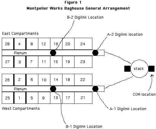
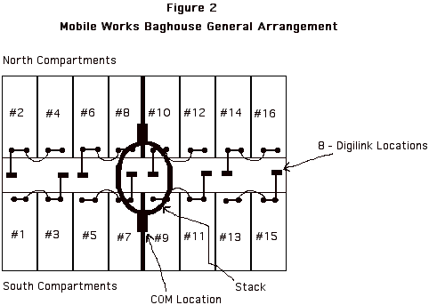
The general configuration of the two EAF baghouses is described in Figure 1 and Figure 2. The Montpelier Works baghouse (Figure 1) is a negative pressure baghouse with a stack (COM required on a stack - EAF NSPS). The Mobile Works baghouse is a positive pressure baghouse with a stack (COM required on a stack - EAF NSPS). A positive pressure baghouse does not typically have a stack, rather the exhaust is discharged through a ridge vent of some type. The particular circumstance at Mobile Works is associated with local regulations unique to Alabama.

Both plants produce steel plate (discrete and coil) as the finished products.


To simplify the diagrams, the location of the fans is not illustrated. The location and design of the BBD system probes is discussed in a later section of this paper.


BBD System Specifications

The BBD systems installed by IPSCO use the DC energized type of probes. Table 2 summarizes the BBD system specifications for the two facilities. Specific locations for detector probes in the respective types of baghouses are discussed in the System Application section of this paper. The BBD system located at Montpelier Works was installed in August 2000, and the BBD system was installed at the Mobile Works in March 2001. Both facilities are greenfield installations, with Mobile Works being the more recent, beginning operations in November 2000.

Table 2
BBD System Specifications Summary
Parameters Montpelier Mobile
Manufacturer: Auburn Systems, LLC Auburn Systems, LLC
Model: TribolinkTM Tribolink TM
Number of Detector Locations: 4 8
Number of Probe Rods/Location: 2 4
Detector Material of Construction: 316 Stainless Steel 316 Stainless Steel
Probe Temperature Range -60 °F to 400 °F -60 °F to 400 °F
Input/Output Interface: PC PC
Operating System Platform: Windows 98 Windows 98


Triboelectric Monitoring Principle

The measurement principle of a triboelectric Broken Bag Detection (BBD) system is based upon measuring the small changes in electrical charge of an energized probe placed within the exhaust gas stream. Generally, there are two types of probe systems presently marketed in this country. Depending upon the manufacturer, the system will use either DC or AC power for energizing the detector probe. AC powered systems claim to have the triboelectric field effected by both particles striking the probe and those passing close to the detector. On the other hand, DC powered systems claim that the majority of triboelectric effect is related to the particles striking the probe. In either case, it is the presence of particles that cause the triboelectric changes.

The probes are generally made of stainless steel or other metallic material that is energized with either the AC or DC electrical voltage. The particulate present in the gas stream strikes the probe (or passes close enough to effect the probe), and the particles act to change the electric field of the probe. This mechanism is similar to the release of static electricity that has been accumulated in a person’s clothing or on the skin surface. The small changes in the electric field associated with the passage of particles are measured in pico-amps. These pico-amp changes are the measurements that quantify the triboelectric signal.

The triboelectric signal is an analog output that is displayed as a percent of scale. The absence of impacting or passing particles is measured as 0%, with the relative increase of particle presence (strikes or near passes) measured up to 100% of the scale.

Because of the sensitivity of the measurement mechanism, the Triboelectric BBD can detect particles as small as 2 microns in diameter . These particles are invisible to the human eye and a Continuous Opacity Monitor (COM).

The particle characteristics of size, shape and structure, as well as the quantity of particles present in the gas stream effect the relative change in triboelectric signal. These factors have nothing to do with directly measuring the density or mass of the respective particle.

The BBD systems used by IPSCO employ the DC based electrical power supply for the probes.

Emission Source and Effect Upon Triboelectric Signals

Since the triboelectric effect is dependent upon changes in an electrical field, the base material composition of the particles has an effect upon this measurement. Certain materials, such as metals, will have a greater effect proportionately upon the triboelectric change than non-conducting materials. Since the measurements being tracked are relative (percent of scale), the output signal can be adjusted to fit a range that provides a signal that the operator can adjust to track the particles being removed by the control device at his location. Iron oxide particles, the majority portion of fume from the EAF steel making and Foundry Furnaces, are a good triboelectric material. However, as noted earlier, there are several factors that effect the triboelectric signal. These include: (1) shape, (2) size, (3) structure, (4) quantity, (5) velocity and (6) chemical composition of the particles. These factors are independent variables that are unique to each emission source and fume control system.

The emission variability between sources is compensated for by adjusting the scale factor of the triboelectric system. Each detector (group of probes) sends a variable signal that is a measurement of the pico amp changes effecting the probes. When the pico amp effect of the particles is greater, the scale factor can be set lower, and correspondingly adjusted if the effect is lower. The output measurement is a percent of the scale factor.

As an example, the scale factor for the Montpelier Works is 1500 pico amps (100% of scale = 1500 pico amps), while the scale factor at the Mobile Works is 250 pico amps (100% of scale = 250 pico amps). Both facilities produce the same type of steel product, and have similar sources of raw materials, however the design of a positive pressure baghouse compared to a negative pressure baghouse effects the velocity and quantity of particles passing the probes during normal operations. Even though the particles have the same basic chemistry, other independent variables effect the triboelectric system measurements at these locations. Correspondingly, each operating facility will have a unique triboelectric signature that will need to be evaluated in setting up the operating and alarm levels for the BBD system at that facility.

Figure 3
Triboelectric Signals - Normal Cleaning Spikes
Positive Pressure Baghouse
Figure 3.1
Triboelectric Signals - Normal Cleaning Spikes
Negative Pressure Baghouse


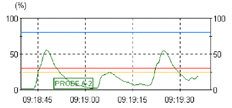
Figures 3 and 3.1 illustrate examples of real time tracking of triboelectric signals for a probe detector on a positive and negative pressure baghouse, respectively. The negative pressure baghouse signal in Figure 3.1 represents cleaning on line, and the positive pressure baghouse is cleaning off line. The spikes shown on each of the signals are referred to as cleaning spikes and are associated with the release of dust that initially passes through a recently cleaned bag until the cake reestablishes on the surface of the fabric. In the case of the on line cleaned row of bags (Figure 3.1), this spike is immediate and trails off over a short period of time. In the case of the off line cleaned compartment (Figure 3) the spike is more discrete and drops off quickly. These figures illustrate the difference between signals of systems that are cleaned on line (negative pressure system) and off line (positive pressure system), however the signals and the respective scale factors will vary from source to source, but the cleaning spike will be present in all systems. Monitoring of signal level and cleaning spikes will be discussed in a later section.

BBD System Application Considerations

There are several factors that should be evaluated when designing a BBD system to monitor a specific fume control system and emission source. The previous section explained the relative triboelectric uniqueness of each emission source. However, the successful and effective installation and operation of a BBD system needs to consider these additional factors:

- The basic type of baghouse system ventilation, positive or negative air-flow through the collector.

- The mechanism for cleaning the filter media (bags).

- Whether cleaning is done off line or on line.

- The degree of broken bag detection/identification. Identification of the bag row or only the compartment.

- The location of probes and number of probes.

- Environmental effects of temperature on the probes and the detectors.

- Signal output monitoring and control. Use of PLC and HMI interface.

- Establishing the scale factor. Determination of what is a normal signal.

- Establishing the alarm levels. Permit conditions that are reportable violations.

- Operator training.

Each of these considerations is discussed in more detail.

Positive and Negative Flow Systems

Generally, the clean side air-flow from the baghouse compartments is monitored by the triboelectric probes. A negative flow system discharges the air into a relatively small cross-section plenum that collects air from a line of compartments, and a positive pressure system discharges into a relative large cross-section plenum or directly to a ridge vent. The velocity of the particles in the negative pressure plenum is typically much higher than those discharging into a penthouse on the top of a positive pressure compartment. With higher velocity, the number of probes needed to monitor a given gas stream tend to decrease. A number of compartments in a negative pressure plenum can be monitored by a single probe location, as indicated in the Figure 1. In the case of a positive pressure system, the individual compartments can discharge directly to atmosphere through a relatively large cross-section (low velocity) pathway. Figure 4 illustrates a typical positive pressure baghouse compartment, and the location for a monitoring probe(s).

Cleaning Method

The cleaning methods for a metal fume baghouse generally use either pulse-jet or reverse flow. Mechanical shaking is not typically used because of the abrasion created in bag folds that develop when the bag tensions are not kept tight. Reverse air cleaning requires that the compartment being cleaned is isolated from the off gas stream so the compartment air flow can be reversed. Pulse-jet cleaned units can be cleaned without isolating the compartment from the off gas. Alternatively, the pulse jet baghouse can be cleaned off line. This alternative for compartment isolation during cleaning will effect how the BBD system monitoring is set-up. The operator of a pulse-jet cleaning baghouse must determine whether his system will use compartment isolation or not during cleaning. The BBD system can be configured to meet either operating scenario.

On Line or Off Line Cleaning

As noted under the previous item, the mechanism of bag cleaning will to a great extent determine whether the baghouse can be operated in an on line or off line method. The reverse air cleaning baghouse can only be operated in an off line method. The pulse jet method of cleaning uses a pulse of high pressure shot into the bag, and as the pulse travels the length of the bag the collected dust is

Figure 4
Positive Pressure Baghouse Compartment Probe Location


shaken from the bag surface as the pulse passes by. This is typically done a row at a time in the respective compartment. When on line cleaning is used, several compartments can be set to have a particular sequence of rows fire at the same time. As an example, a baghouse with 10 compartments, 12 rows of bags per compartment, can on line clean compartments 1 and 3 at the same time interval. Provided that these compartments deliver off gas to a different plenum to avoid having mixed cleaning signals striking a probe during the cleaning cycle.

Off line cleaning of a pulse jet baghouse generally reduces the number of probes needed to monitor the system. The ability to identify single rows with broken bags is not lost, however the programming must be modified to make such determinations if desired by the operator. This consideration is discussed in the next section.

The number of probe groups for a reverse air cleaned baghouse (off line cleaning required) can also be zone configured, however the total number of compartments in the baghouse will directly effect how many zones can be established.

Degree of Broken Bag Location Detection

Ideally, it would be desirable if a BBD system could identify the specific bag that is leaking or broken, however even though this could be done, the cost to accomplish it would be prohibitive. More cost-effective detection can be accomplished using a select number of locations, depending upon the type of baghouse at the particular facility attempting to install BBD technology.

A facility with a reverse air cleaning, positive pressure baghouse, must use the off line compartment cleaning method for this type of unit. Since the BBD system will be monitoring the exhaust characteristics of the compartment when it is returned to service after cleaning, it is monitoring the contribution of all the bags in that compartment. The system can identify the compartment containing a leaking bag or bags. It will require isolation of the compartment and entry by an operator to visually identify the bag or bags that need replacement or repair.

As noted in the previous section, a pulse jet baghouse can be cleaned in either the on line or off line method. When cleaning on line, the baghouse PLC cleaning information can be coordinated with the BBD signals to identify the particular row that contributed to an alarm signal at that probe location. This data can be sent to an alarm file for operator reference. An operator reading the alarm file can identify the particular row containing the broken bag or bags, reducing the number of bags requiring visual inspection to only that row. In a compartment with 10 rows of 10 bags per row, the operator would need to inspect only 10 bags when the row is known. If only compartment identification was known, then all 100 bags would need to be visually inspected.

A pulse jet baghouse that cleans off line can still identify the row of suspected leaking bags. However this would require programming in the PLC to flag the compartment when it returned to service with an early warning alarm level, and designate this compartment for on line cleaning during the next scheduled cleaning cycle. The method of row identification would be part of the programming during the on line cleaning cycle. Once the row has been identified, the operator could make the visual inspection to locate the leaking bag or bags.

Probe Locations and Number

Location:
Probe locations are determined by the number of zones a baghouse can be subdivided into while detecting individual compartment off gas triboelectric signals during operating and cleaning cycles. The factors of on line and off line cleaning have been discussed previously.

In a pulse jet, negative pressure baghouse, multiple compartments can be on line cleaned in the same plenum, provided the plenum has multiple detector locations that can distinguish between the compartments being cleaned. In the case of the Montpelier Works baghouse, the two exhaust plenums have been divided into 4 zones. One compartment in any of these 4 groupings could clean simultaneously: (1, 2, 5, 6, 9, 10, 25, 26); (13, 14, 17, 18, 21, 22); (4, 3, 7, 8, 11, 12, 27, 28); (15, 16, 19, 20, 23, 24). As an example, compartments 1, 13, 4, and 15 could be on line cleaning and be effectively monitored by the BBD system. However, 2 compartments in the same group could not be cleaned on line since the triboelectric probe could not distinguish between the output from compartments 1 and 2.

For a baghouse that will be cleaning on line, the number of compartments simultaneously cleaning will directly effect the number of detector zones installed in the BBD system. Generally, the more cleaning zones, the more detectors needed for the baghouse.

For positive pressure baghouse systems, the design of the ridge vent will determine how many zones can be established. Baghouses can generally have two types of vents, either a continuous ridge vent (CRV) running along the center line of the structure or a series of circular vents along the center line, combining the exhaust gas from groups of compartments. As noted previously, only whole compartment exhaust gas can be monitored on positive pressure baghouses.