by Walter Anderson
An introduction to the equipment and procedures to produce high speed
photographs
by Walter Anderson
The Amateur Scientist Photo Contest was won by an image of a sock travelling at 450 mph (1). This image rekindled an interest I once had in high speed photography. I decided that my first foray into this field would be to reproduce Dr. Harold Edgerton's classic milk drop photograph.
Dr. Edgerton, a professor at MIT, invented the electronic flash and used it to produce a number of famous photographs. These include a 22 caliber bullet slicing through a playing card as well as the crater made by a single drop of milk. I chose to reproduce the milk photograph because it required a relative slow flash to freeze the action.
The first step in producing a high speed flash photograph is to determine how fast the flash needs to be. For the milk drop photograph this process begins by estimating how fast the drop is moving when it hits the surface of the milk. I made several assumptions; height the drop would be released from is one meter, air resistance would be ignored. These two assumptions would provide a reasonable upper limit on the velocity of the milk drop.
The total time, t, that it takes the drop to fall one meter is given
by the formula ![]() . Evaluating this equation when distance, s, is one meter, and gravitational
force, g, is 9.8 meters per second per second, yields a total time of 0.45 seconds. The
final velocity can be estimated using the equation v = gt. Evaluating this equation for
t=0.45 seconds yields an estimated final velocity of 4.4 meters per second.
. Evaluating this equation when distance, s, is one meter, and gravitational
force, g, is 9.8 meters per second per second, yields a total time of 0.45 seconds. The
final velocity can be estimated using the equation v = gt. Evaluating this equation for
t=0.45 seconds yields an estimated final velocity of 4.4 meters per second.
I am going to assume that a normal 50mm lens will be used. The lens will be between 45 to 60 cm from the milk crater. My lens has a magnification of approximately 1:6 with this arrangement. This means that a object 6 cm in size at the focal point will be 1 cm on the film. To obtain a sharp photograph I do not want the drop to move more than about 0.35 millimeters on the film. This means that the drop can not travel more than about 0.22 millimeters during the flash. At 4.4 m/s that means the flash duration must be less than 500uS. This is a fairly long flash and may be obtainable with ordinary detachable flashes. See the section on testing flash speed to determine the speed of your flash.
Do not attempt to construct or modify this circuit or any other flash circuit unless you have considerable experience with high voltage circuitry. Flash circuits deal with voltages and currents that are potentially lethal. If in doubt use a commercial high speed flash!
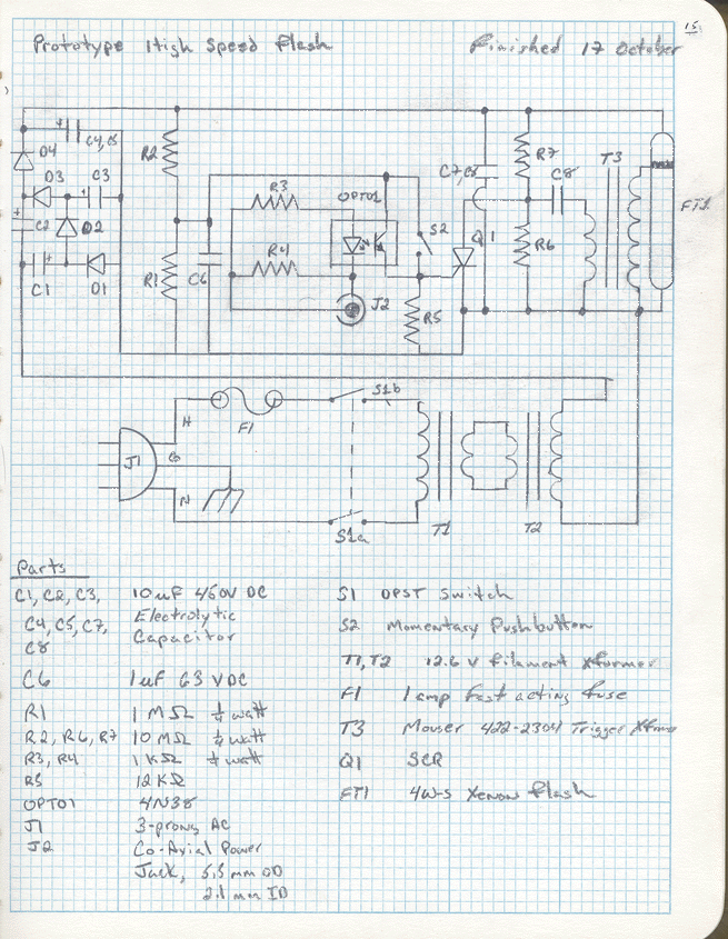
My prototype flash circuit uses a four stage voltage multiplier was used to produce approximately 620V. A three wire plug is used with the ground wire connected to the chassis. Two filament transformers are connected back-to-back to provide a makeshift isolation transformer. The circuit is triggered through an optoisolator. The optoisolator triggers the gate of a silicon controlled rectifier (SCR) which discharges a small capacitor through the trigger coil. Since trigger coils are designed to operate with a primary voltage of approximately 300 volts a voltage divider is used to lower the main voltage to an acceptable level. I only had electrolytic capacitors rated for 450 VDC. I used two 10 microfarad 450V capacitors in series to achieve a effective capacitance of 5 microfarads at 900 V. The energy output of a flash circuit can be estimated used the formula P = 0.5*C*V*V. Using this formula this circuit should produce a flash with 0.96 Joules (Watt-Seconds) of energy. My biggest concern with this circuit is that two capacitors in series have a fairly high ESR (effective series resistance). A high ESR would tend to produce a fairly lengthy flash pulse.
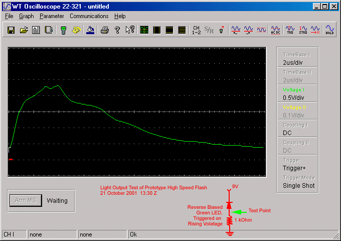
A reverse biased Green LED was connected in series with a 1 kOhm resister and a 9 volt battery. A digital storage oscilloscope was used to measure the light curve shown in the figure below. The circuit used was drawn on this figure. As you can see from this figure the voltage curve drops below 0.5 volts within 80 microseconds. You can find additional information about flash circuits, including more schematics, components sources, and safety information from reference number 3
A high speed flash is only half of the equipment needed to produce the desired high speed photograph. The other component that is needed is a means to trigger the flash at the appropriate time. In preparing for this I exchanged a number of emails with Joseph DiVerdi, the photographer of the ballistic sock mentioned in the introduction. Mr. DiVerdi has a web site with a considerable amount of technical information on the equipment and process that he used to produce the winning photograph.(2) Mr. DiVerdi used a design for a Photo Gate that he obtained from the CMOS Cookbook by Don Lancaster. My initial attempts to reproduce this circuit were unsuccessful. I initially tried to use a matched pair of infrared phototransistors/LED that I obtained from Radio Shack (Part Number 276-142). When I replaced the phototransistor with a L14C1 that I obtained from Digikey (Part Number L14C1-ND).
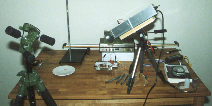
Before proceeding much further, I wanted to perform an initial test to verify my calculations and to determine what exposure might be required. While the test must be conducted in a dark room the room does not need to be as dark as a traditional photographic dark room. I used my dining room, I performed the tests at night with subdued lighting; however, I could clearly see the dish and photogate once my eyesight adjusted after a few minutes.
The photo at right shows the setup that I used to perform the initial test. The light source for the photo gate is a laser module mounted on a three point stand. The beam is positioned so that it is just over the top of the tray.
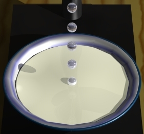
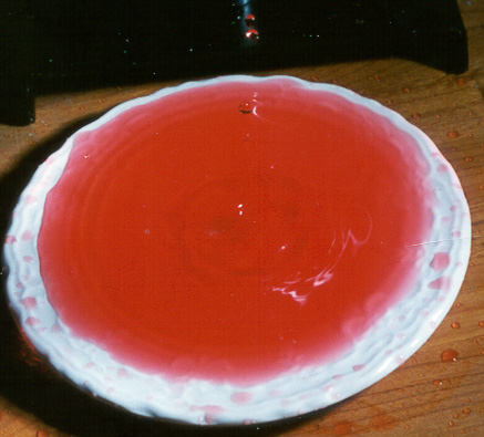
The output of the photogate circuit was used to directly trigger the flash circuit. A Pentax ZX-M camera with a 50mm f/2 lens was loaded with Fuji X-TRA 800 speed color negative film. Aperture from f/2 through f/22 were tried and all produced acceptable prints. Of 21 exposures 5 produced images that froze one or more drops. None of these images produced the desired photograph; however, the five images of the drops did demonstrate that the the flash was fast enough to produce a sharp photograph. An example of these five photographs is shown below. Several shortcomings of the process were identified. First the separatory funnel that I was using did not appear to produce uniform or easily controllable drops. Second the triggering circuit required a greater level of control.
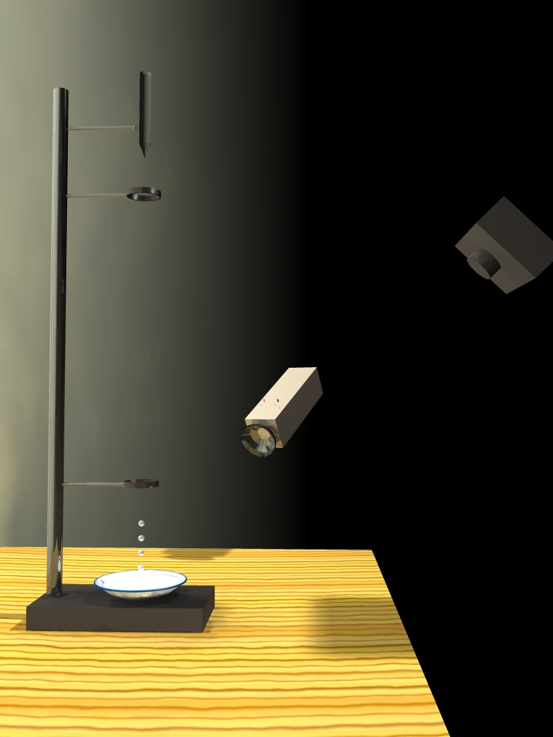
The above equipment is placed on a table as shown in Figure 1. This is done in a room that can be made very dark. I used my dining room at night. The room need not be as dark as a photographic darkroom.
This page and all of its contents are Copyright © 2002 by Walter Anderson
Home Page