INTRODUCTION
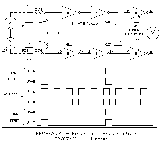
The ProHead - v1 circuit shown in Figure 1 is an unusual voltage controlled
symmetry oscillator (VCSO) with a control range of 0V-Vcc. The frequency
is relatively independent of the absolute light level. The pulses are equal
duration when the control voltage is at Vcc/2. With this symmetrical square
wave the average DC output voltage at Vcc/2. When driven by a symmetrical
square wave, the difference of the average DC voltage between two
complementary outputs is zero and with these outputs connected across a
motor winding the average motor rotation is also zero and motor current
is reduce to the minimum. This is the condition when the light on the two
photo sensors is balanced and is represented by the "centered" waveform
.

A simple LDR or PD photo sensor bridge connected between 0V and Vcc with equal light level on the two sensors has an output voltage at the midpoint equal to Vcc/2 . This is precisely the level required by the VCSO for zero motor rotation. When the light level on the two sensors is unequal, an error voltage is generated at the bridge output equal to the actual voltage at the midpoint minus Vcc/2. As a result the duty cycle changes and a waveform is generated across the motor windings with a DC component proportional to the light difference. This voltage across the motor is either predominantly positive or negative as shown in the turn left / turn right waveforms. The system uses this difference signal to correct photo sensor the error signal and therefore the system acts like a "light balancing" servo mechanism or HEAD with one degree of freedom (1DOF). Because the output signal is proportional to the light difference, the motor rotation slows when approaching the balance point, this reduces overshoot compared to some simpler ON/OFF head control circuits. This can be used to advantage in 2DOF system where the mass and inertia of the head assembly is significant and if not compensated for, can lead to endless servo hunting. which indicates that . As a point of interest, all beam heads respond by balancing the light in the field of view of the two sensors i.e. .the head is pointed either at a bright light contrasted by a dark background or may simply point at a uniform background and happily ignore a brighter light outside the field of view.
NON INVERTING BICORE
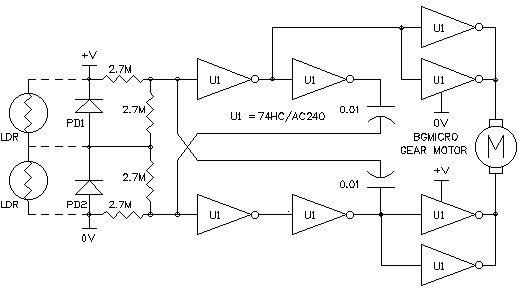
The ProHead design is based on the non inverting bicore (NBC - also
know as the rigter oscillator) which, as shown in Figure 2, is somewhat
related to the grounded bicore. The two separate resistor/capacitor (R/C)
networks and gain stages (Nvs) are used independently control the ON and
OFF time of the oscillator outputs. The outputs of the two non inverting
gain stages of the NBC are always in phase.

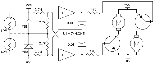
Normally a head motor is driven from two out of phase signals e.g. the
complimentary outputs of a grounded bicore) . In Figure 3 , a 74HC240
ProHead - v1 is shown with 4 inverters used in parallel as motor drivers.

In order to develop a voltage difference voltage across a motor motor one of the NBC outputs has to be inverted. As with the 74HC04 version, each of the two non inverting stages uses two 74HC/AC240 inverters in series to provide double inversion. The two remaining inverters are used as motor drivers with the inputs connected as shown to provide the necessary complementary outputs. The tri-state enables can then be used to implement a low power standby mode required for solarized application.
VOLTAGE CONTROLLED DUTY CYCLE
Each of the two Nv neurons of the NBC has a time constant determined by the R/C components and by the reference voltage each the resistor. Since one resistor is normally referenced to 0V and the other to Vcc, they behave opposite to a change in reference voltage. The GND referenced Nv (-Nv) time constant increases when the reference voltage goes positive towards Vcc/2 but the Vcc referenced Nv (+Nv) time constant increases when the reference voltage goes negative towards Vcc/2. At Vcc/2 (or rather the threshold voltage of the logic chip) the pulse width approaches infinity. When connected with two bias resistors which limit the control voltage at the gain stage inputs to Vcc/2, a single control voltage can simultaneously influence both Nvs. When the control voltage is at Vcc/2 the effect is equal on both Nvs and the NBC output is a symmetrical square wave. At extreme control voltages of 0V and Vcc, the respective +Nv or -Nv time constants approach infinity and the NBC output is continuously at 0V or Vcc for corresponding to 0% and 100% duty cycle with respect to 0V referenced loads and to +100% and -100% to complementary output loads such as the head motor.
OTHER APPLICATIONS
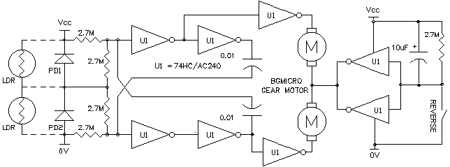
The outputs of the ProHead - v1 can also drive two separate motors of
a wheeled photovore to provide a differential speed control proportional
to the difference in light balance on the two photo sensors. As shown in
the ProVore - v1 in Figure 3, a 74HC245 non inverting buffer
is used for the basic NBC and two complementary transistors provide the
necessary inversion and current drive to control much larger motors. Don't
let the similarity to a normal bicore fool you, with a good look at the
schematic and some analysis of the signals, this design will reveal
quite different circuit operation and behavior.


enjoy
wilf