INTRODUCTION
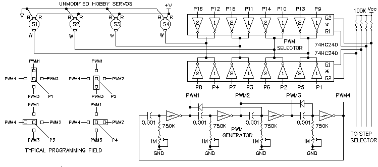
In contrast to the all digital approach shown in the EPROM CORE servo controller, the ProServo design uses familiar BEAM techniques.The design is an extrapolation of the HC240 mux reverser (not the Matt Mux) and uses four HC240, two 74HC14 and one 74HC139 to control four unmodified hobby servos. The ProServo is programmed via multiple pin header and shorting plugs.. The ProServo circuit consists of five subsystems which can be summarized as follows:
1. The Pulse Width Modulation (PWM) Generator uses a microcore
to generate four fixed width PWM pulses corresponding to four servo positions.
2. The PWM Selector uses two 74HC240 chips to select four groups of
four servo positions.
3. The two speed Step Generator uses a microcore to generate
a four step sequence to control the PWM Selector
4. The Step Selector uses two 74HC240 chips to select one of five step
sequences corresponding to Forward, Reverse, Left Right and Pause. A momentary
panic switch closure changes the overall speed of the walker to escape
velocity.
5. The Sensor Encoder uses the output of four switches to control the
Step Selector
Both the PWM Selector and the Step Selector can be programmed with jumpers
and potentiometers until these circuit parameters have been optimized.
After fine tuning, these adjustable components can be replaced with
eqiuvalent fixed components. The circuit is shown in its functional form
in Figure 1 and 2 . The IC pin numbers and power supply connections will
be shown in the next drawing revision.

PWM GENERATOR
The ProServo/4 design can control the rotation of 4 unmodified hobby servos to 4 pre-programmed positions. It consists of a PNC free microcore with the 4 Nv pulse widths adjusted between 1ms and 2ms. The pulse refresh rate is a150 Hz and the output pulses are active low signals.
PWM SELECTOR
The four Nv pulse outputs of the PWM Generator are connected to the
servo inputs through 4 groups of 4 inverters using two 74HC240. The
PWM selector is programmed by connecting the PWM1-4 Generator outputs to
each of the P1-16 PWM Selector inputs as shown in the typical programming
field of Figure 1. The PWM selector enables the active high outputs of
each group of 4 PWM signals to the servo motor control inputs. One of the
four groups of 4 is enable at a time by a control signal from the
Step Selector outputs.

STEP GENERATOR
In Figure 2, the Step Generator uses a PNCfree microcore to generate a 4 sequential active high output pulses which are used to generate a complete stride of the walker. As the 4 pulse sequence is repeated, the robot takes multiple strides. The duration of each step can be adjusted with 1M potentiometers. Overall speed can be adjusted with a 100K master speed control. A Panic switch is provided which bypasses the master speed adjustment and causes the Step Generator to operate at maximum pulse frequency for the walker to escape danger as quickly as possible. The four Nv pulse outputs of the Step Generator are connected to the S1-16 Step selector inputs of 4 groups of 4 inverters.
STEP SELECTOR
The Step selector is programmed by connecting the Step1- 4 Step Generator
outputs to each of the S1-16 Step Selector inputs similar to the arrangement
shown in the programming field of Figure 1. The active low Step Selector
outputs invert the Step genrator output pulses. The Step Selector outputs
are connected to the enables of each group of the PWM Selector.
One of the four groups of 4 Step Selector outputs is enabled
at a time by the 4 outputs of the 74HC139 Sensor Decoder.
SENSOR ENCODER
The Senesor Decoder generates one of 4 Step Selector enable signals. The A and B binary inputs select which output is active low. The A and B inputs are controlled by the conditioned output of the Left and Right switches. The 74HC14 Schmitt triggers and a R/C network are used as Nu neurons to stretch the action of the Left/Right switches. When both Left and Right switches are closed as might occur when the walker is "cornered" the Reverse function is selected. The reverse switch activates the Left/Right switches and also selects the Reverse function. The Stop button and Nu causes the walker to Pause for a few seconds and "play dead". A toggle switch can be used in parallel with the Stop button to diable the controller PWM signal generator.
FUTURE PROSERVO
The basic ProServo design can be easily expanded as follows:
1. Control of 8 servos requires 4 additional 74HC240 chips.
2. The PWM generator can be expanded to 6 or 8 PWM unique posistions
which requires one additional 74HC14 chip
3. The PWM selector can be expanded from the existing 4 groups to 6
or 8 groups which requires 1 or 2 addtional 74HC240 and one
additional 74HC14 chip.
4. The Step Generator can be expanded to 8 steps with one additional
74HC14 chips
5. The Step Selector and Sensor Decoder can be expanded to by two additional
sensors and step patterns by using the spare 74HC139 decoder and two additional
74HC240 chips.
For some applications an alternative method of expansion simply duplicates the ProServo/4 design to independently or interactively control 8 servos.
wilf