- Set the UCSFOLLOW
- UCSFOLLOW - 0 - this prevents the view from "following" the UCS
- Set the UCS
- UCS - Restore - Top
- DDInsert
- Block- Top - @ 0,0,0 and Explode
- Convert to Closed Polylines
- PEDIT -
Convert to PLINE - Join (repeat as needed)
- Set the UCS
- UCS - Restore - Front
- DDInsert
- Block- Front - @ 0,0,0 and Explode
- Convert to Closed Polylines
- PEDIT -
- Set the UCS
- UCS - Restore - RSide
- DDInsert
- Block- RSide - @ 0,0,0 and Explode
- Convert to Closed Polylines
- Tip: RSide
profile must be edited. Trim the front vertical line at the horizontal intersections, removing the portion in between. PEDIT - Convert to PLINE - Join (repeat as needed)
- UCSFollow
- 0 (this prevents the view from following the UCS.)
- Set the UCS
- UCS - World
- Set to SW Iso View.
(MDT Accelerator Key - 8)
- Extrude Top View to Hgt of 10 and RSide to -10.
- Interfere
(select one extrusion, then the other) Make Interference Solid. Delete RSide and Top solids.
- Extrude Front View to Hgt of 10.
- Interfere
(select front extrusion, then the previous solid) Make Interference Solid.
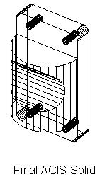
Delete Front solid. Subtract holes. The result is shown below:
|
|