 I have good news and some better news. The good news is that Mechanical Desktop 5 adds many new, useful features. The really good news is that
the basic functions, menus, and toolbars remain virtually unchanged and do not have to be relearned.
I have good news and some better news. The good news is that Mechanical Desktop 5 adds many new, useful features. The really good news is that
the basic functions, menus, and toolbars remain virtually unchanged and do not have to be relearned.** AJ's comment about MDT6, MDT7(2004?) released since Bill Fane wrote this article.
I feel that Bill's comments about the similar layout of MDT5 to MDT4 now applies equally to MDT6. Its only when I can't see a button on a particular toolbar or a selection option in a particular menu that I realise that I am in A2000/MDT4. A2000i/MDT and A2002/MDT6 just added "features" some useful, some not so useful. A2000/MDT4 was the core new release and I understand listening to others that A2004/MDT7 (or MDT2004 or whatever) is much the same ..new features and the introduction of something that is described by many as 'encryption' which must poise problems for the user in the long haul.
The compression that is promoted as resulting in 'smaller faster files with a 50% saving' may have the end result of smaller files and faster transmission over the internet but this 'feature' materially slows up opening and saving files in routine work as you decompress and compress files each time. As ADesk choose not to make the delay times known I do not feel uncomfortable saying it takes"twice as long to open and save files. That has a certain symmetry with their 50% saving (I think Dotson has published figures on his website).
I have good news and some better news. The good news is that Mechanical Desktop 5 adds many new, useful features. The really good news is that
the basic functions, menus, and toolbars remain virtually unchanged and do not have to be relearned.
Many of the new features appear simply as additional options under existing commands. Mechanical Desktop 5 runs under AutoCAD 2000i. This is not really a major new release of AutoCAD, so everything should be pretty stable by now. The main features that Mechanical Desktop 5 draws from 2000i are the new Internet capabilities for collaborative design work over the Internet or an intranet. In an assembly, for example, externally referenced part and subassembly files can reside anywhere in the world. Anyone who has the proper access rights can open any file from anywhere and always get the most current information—no more couriered or e-mailed files that tend to get out of sync.
Even better than that, Mechanical Desktop uses standard Windows NetMeeting technology. This means that other people can peer over your shoulder from anywhere in the world to watch you work, and you can pass control over to them so they can run your copy of Mechanical Desktop remotely. They don't need to have AutoCAD or Mechanical Desktop installed.
The Power Pack from Mechanical Desktop 4 is no longer an option, but now ships as standard. Because both Mechanical Desktop and Power Pack are AutoCAD add-ons, you can choose to run any combination of plain AutoCAD 2000i, Mechanical Desktop 5, Mechanical Desktop Power Pack, and the 2D Mechanical Power Pack.
The interface
As I indicated earlier, the basic interface has hardly changed, but the changes are significant. For starters, 3D Orbit is now a transparent command that you can invoke from within any running command, just like Zoom and Pan. In Figure 2 below, notice that 3D Orbit is running within the Line command. When you terminate 3D Orbit, Line resumes. 3D Orbit also now includes lighting controls, much like those in the AccelView viewer of early Mechanical Desktop releases. Figure 3a shows the dialog box that sets the lighting controls.
 |
| Figure 1. While you edit a component within Mechanical Desktop, other components turn (?) |
 |
| Figure 2. 3D Orbit now runs transparently. Here you see it running within the Line command. |
The two sliders control light intensities. The Ambient slider controls the overall diffuse light, such as outdoor light on a soft, cloudy day. Changing it controls the overall brightness (Figure 3b). The Direct slider controls the intensity of a single, directed spotlight. Its effect is to adjust the contrast or relative brightness between lighted and shaded areas. In Figure 3c, I turned direct light up bright and the ambient level down. You can use the light bulb and arrow button to aim the directed light, as shown by the shadows in Figure 3d. You can change lights transparently within 3D Orbit, so it becomes easy to get your presentation screen capture just right.
 |
|
| Figure 3a. 3D Orbit now includes lighting controls. | Figure 3b. Ambient is turned up bright. |
 |
 |
| Figure 3c. Ambient is turned down, and direct is up. | Figure 3d. You can change the aim of direct light. |
The number-one interface improvement is—drum roll, please—the Browser Hide function. It frees up large amounts of screen real estate. Right-click in the Browser's gray background area and select Auto Hide, then Collapse. The browser collapses to a small header bar (Figure 4a). Now, when you move the cursor over the header bar, the full browser automatically pops back up (Figure 4b). It collapses back to the header when you move back out into the drawing area. You can also set it so that the Browser completely hides to the left or right of the screen. When you move the cursor to the appropriate edge of the screen, it reappears.
(** I don't recall this in MDT6 so I'll look at it. I'm happy with MDT4 where you double left click on the grey area at the top and then 'park' it up like a top . From then on double left clicking in the same place drops it down or pulls it up like a blind when required. Don't like the idea of it collapsing just because you move the cursor off it. -aj)
 |
 |
| Figure 4a (left). You can collapse the browser to a header bar, and it pops back up (Figure 4b, right) when the cursor runs over it. | |
Another new interface feature should appeal to those who build large assemblies. If you have trouble distinguishing a specific part, simply right-click on its name in the browser, then right-click on Zoom at the top of the pull-down menu. This immediately zooms the drawing view so that the selected part fills about 80% of the screen (Figure 5) (** I don't recall this in MDT6 so I'll look at it -aj). Mechanical Desktop 5 permits each feature in a single part to have its own color. This makes it much easier to interpret how a complex part is built (Figure 6). You can carry the feature colors into the 2D drafting views. Also, as part of Mechanical Desktop 5's 2000i functionality, you can now control the style, size, and color of the UCS icon.
 |
 |
| Figure 5. You can zoom directly to a selected part from within the Browser. | Figure 6. Features can be assigned colors different from those of the base part. |
Part modeling
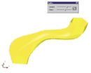
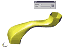
Mechanical Desktop 5 now supports open profiles and thin extrusions. The part in Figure 7a is formed from the single-line sketch profile shown in the upper half of figure 7b. Earlier releases required the profile shown in the lower half of Figure 7b. Open profiles and their extrusions greatly simplify the sketching and constraining of thin parts and are
ideally suited for sheet-metal shapes.
 |
 |
| Figure 7a (left). You can create thin parts from a single-line profile (Figure 7b, right), instead of having to create a double-line profile. | |
When you create an extrusion from an open profile, the dialog box prompts for the usual extrusion distance, operation, and termination values. It also asks for the thickness of the extruded material and the extrusion type. The latter option lets you choose how the material thickness is applied: equidistant midplane, all one way, or a different value for each side.
As usual, you can use the regular Boolean operations of join, cut, and intersect when combining a thin extrusion with an existing part, as shown in Figure 7c. You can also use open profiles to quickly and easily add ribs, walls, and shelves to a part.
 |
| Figure 7c. In Mechanical Desktop 5, you can still use Boolean operations to combine thin parts with existing solids. |
3D Text
My May 2000 Learning Curve column describes in great detail how to generate 3D solid text on a solid model. This is often required in castings and injection molds. Well, that column is now obsolete (** not for AutoCad or MDT4 and earlier users -aj). Mechanical Desktop 5 lets you create a TextSketch object. This is a single object whose size, location, and orientation angle you can dimension and control parametrically like any other sketch. Figure 8a, took less than two minutes to create.
You can use any standard Windows TrueType font in any style, and you can specify a draft angle. You can edit the font, style, content, and Boolean operation of the text item. It took about 30 seconds to turn Figure 8a into Figure 8b.
 |
 |
Figure 8a. You can produce solid text from standard TrueType fonts. |
Figure 8b. You can parametrically edit solid text like any other solid object. |
Do you want to get bent? Mechanical Desktop 5 now lets you take an existing part and bend it. You use an open profile to specify the bend location, and you can parametrically dimension and vary the bend location and radius.
Figure 9a shows a flat piece, and Figure 9b shows the result of adding a bend. In this case, the open profile consisted simply of a single line across one leg of the part. Figure 9c shows the result of parametrically increasing the length of the bend line until it touched the second leg.
 |
 |
 |
| Figure 9a (left). Mechanical Desktop bends flat pieces, and you can parametrically adjust the bend line (Figure 9b and 9c, middle and right). | ||
As you would expect, you can parametrically control the angle, radius, and side of the bend. You can suppress bend features to show the flat development of the part. This will be of great value to those who design sheet-metal parts, but it still has a long way to go because you must work in reverse.
With Mechanical Desktop 5 you create the flat development first, then bend it. It may take a bit of trial and error to end up with the final part you want. If you want to see how sheet-metal development should be done, take a look at Autodesk Inventor.
The Equation Assistant has a very useful new feature. Whenever you need a dimension value, you can launch the Equation Assistant to help build intelligent dimension values. In Mechanical Desktop 5, you can now create new named variables as you need them from within the Equation Assistant. Previously, you had to predefine them before you could use them.
The Mechanical Desktop array function is significantly improved. Actually, it's now three separate ones: Polar, Rectangular, and a new Axial array function. The last lets you create a polar array in which each succeeding copy also moves up incrementally along the axis.
Come together
Assembly modeling has added only two significant new features, but they are both real winners. For starters, you can now edit subassemblies and combined parts in place within the context of the assembly.
A magical feature is that you can use the Browser to drag and drop constrained parts from within an assembly to and from subassemblies without losing constraints. You can build and constrain an assembly at one level, then go back and reorder it into suitable subassemblies.
 |
 |
| Figure 10a (left). Assembly models can now be restructured into subassemblies without disturbing the constraints (Figure 10b, right). | |
Figure 10a shows the before shot of the Browser, and Figure 10b shows it less than two minutes later. Note the complete rearrangement into nested subassemblies—I didn't have to add or change a single constraint. This one feature alone makes Mechanical Desktop 5 worth the price of admission.
Skin deep
If you use surface modeling at all, you will be pleased with Mechanical Desktop 5's new and improved features. They fall into two categories: a group of functions to analyze, edit, stitch, and repair surface models, and a single function that lets you take a single, open-face surface or quilt and thicken it into a standard Mechanical Desktop solid part of any specified thickness.
A picture is worth..
Mechanical Desktop 5's 2D drafting views feature a couple of interesting additions. As noted earlier, individual features on the solid can now have their own colors, and those colors can carry over into the 2D drafting views. In addition, you can use design variables from the solid modeling side within the bills of materials, parts lists, and general intelligent notes. You can then use a design variable to change the size of solid parts, the raw material size in the BOM, and the name in the drawing title block. All in all, Mechanical Desktop continues to mature gracefully, unlike the writer of this review. Highly Recommended.