
Taken verbatum from www.mycad.com MDT Faq (specifically 2202 and 2210)
Q: How do I Generate & Control a circular a hole pattern?
A: Well we'll assume you already know how to make a circular pattern using AMARRAY so to make it controllable so you can parametrically alter the start angle of the first hole as well as the offset from center is really the question at hand.
You can start off with your round part and place a work point representing the first hole. You then want to add constraints to this work point so that it goes where you want it to be. Before doing this you should make 2 design variables being "offset" and "Startangle", where offset is the starting holes offset from the center of the part and the start angle is that starting holes angle with respect to the horizontal or vertical.
Place your sketch plane of the top face of your part and place the workpoint in the top right quadrant. Next you want to add 2 dimensional constraints as such.

Next place your first hole using "on point". and lastly use the AMARRAY to array the hole to generate your pattern.
There is a second alternative to doing this listed at below:-
Q: How can I place a hole at a given Distance & Angle (2210)
A: There are different approaches to placing a hole at a given distance and angle and the example i will show allows you do do this while resulting in a correctly dimensioned 2D dwg when that time comes. There is another alternative listed at MDT FAQ 2202
The first step is to generate your round profile, however we will also include some construction geometry that shows us the location of the first hole. Putting the construction geometry allows us to edit the entire profile and hole location within one easy to edit sketch.
It is advisable to start a model of this sort with 3 grounded workplanes located at 0,0,0.
The bolt hole dimension should be a Radius and not a diameter for simplicity later on.
The sketch geometry is as follows with both the circles drawn at 0,0
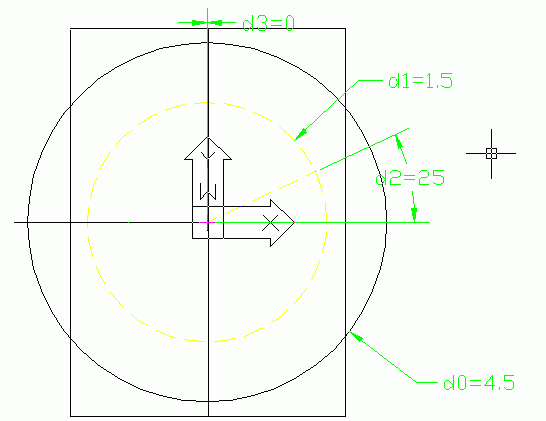
Next, extrude your model and then apply a work axis down th middle. The next step is to place a workplane using On-edge/axis and Planar angle. The angle value in this case will be "d2" referenced from the original sketch.
When placing the workplane, select the workaxis at the first prompt and the horizontal workplane as the second prompt. The result should look as follows:
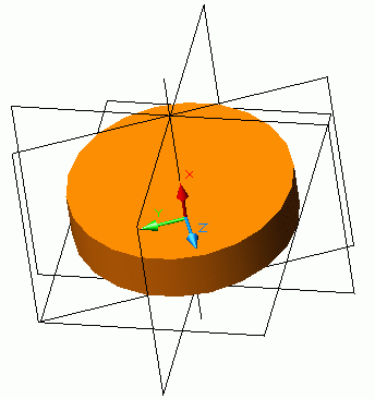
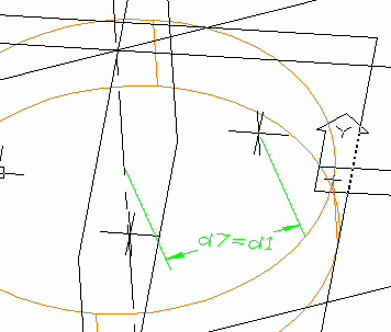
With our point located properly, we can now place a hole with its location
based "on Point". With our first hole located, we can then proceed to array
the hole wo make our hole pattern. In my case I made a total of 6 holes
in a full circle.
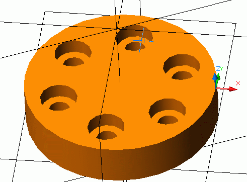
To test it out, return to edit your original sketch and edit the angle of the location as well as the bolt hole circle radius. Your model should update to show these changes.
When you generate your drawing views, you will se that you now have some (green) PARDIMS that locate the hole as you would want it dimensioned.
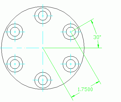
Jun/02/03 MDT6 DiscussionTopic: Locating a workpoint on a bolt circle!
Hi Kevin
I usually sketch a work-axis (RMB in browser and choose "edit" to constrain
it to existing geometry) at an angle, then project-constrain a workpoint to
this work-axis and dimension it to the centre. You might need a workplane or
a horizontal work-axis to be able to dimension the angled work-axis,
depending on your geometry. -Per Engberg