Taken from MDT Tips and Tricks in Drew Fullford's www.mymcad.com (click on MDT in the top navbar).
We will be investigating using a few of the less commonly used commands of Mechanical Desktop being Split Lines & Face Splits.
For our simple excercise we will be projecting some profiles at various angles. The excercise has no true practical use but you should get a better understanding of where and when these commands can be used. In this example we will project a profile at a given angle so that the projections are parametrically linked to the source or unprojected profile. we will then generate a solid from that projected profile.
We will be using split lines (AMSPLITLINE), and face splits (AMFACESPLIT) to make a part who's profile was a result of a projected profile. This excercise can be done in MDT 3 as well as MDT 4.
Lets begin...
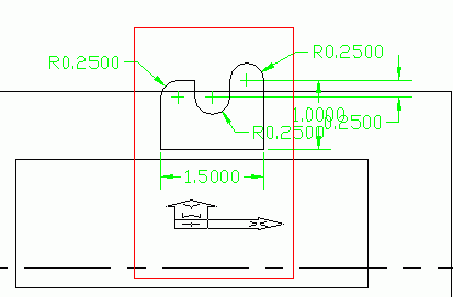
Here is the profile we wish to project. We will start with an assumption that our projection angle will be with a range of 0 to 75 degrees.

Commence by making a workplane AMWORKPLANE on the world XY and then a horizontal work axis on that workplane. To place the work axis use the AMWORKAXIS command and simply select the command line option to "SKETCH" it and draw a close to horizontal line. Next place a new workplane with modifiers of edge/axis and planar angle. For the angle value, enter the maximum projection angle of 75 degrees. Select the workaxis as the first selection and the workplane as the second option. Your sketch plane should now be on the new workplane. If not, put it there.
Make your view planar to the sketch plane using the SKETCH VIEW Command from the Mechanical view toolbar Draw the geometry above on the new workplane and then use the AMSPLITLINE command.

This solves the profile like a normal sketch and you can add the constraints required as normal. Solve for your fully constrained sketch.
Next (without changing views), place your sketch plane on the other workplane which should be visible and accept the defaults. Your UCS Icon should indicate the change. Now draw a rectangle (shown in Red below) to encompass your existing profile and make sure it goes lower than the work axis.

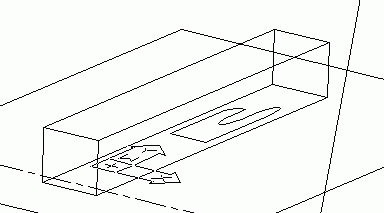
Now run the AMPROFILE command and select the new rectangle. You don't need to constrain this, so go ahead and extrude this by the amount we want our main extrusion to be. In our case the value is 2.
Next run the AMFACESPLIT command as shown below and choose the "pRoject" command line option and select the bottom face of the square slab we had created as the face to split.

Turn off shading and you will see the pattern engraved onto the bottom of the slab as shown below.

Next you will invoke the AMPROFILE command as such.. (You should zoom in first to make selection easier)
Command: AMPROFILE
Select objects for sketch: <press return here> *** Do this extra Enter before you start picking! -AJ ***
Select part edge to close the profile: <select an edge of our projected pattern>
Select part edge to close the profile: <repeat until all 9 edges are selected & highlighted>
Select part edge to close the profile: <press return>
Solved fully constrained sketch.
Computing ...
Now we perform our main extrusion of our profile. Extrude the profile, Intersecting, through the part. The desired result is shown below.

Now to test it out, we can double click on workplane2 in the browser and adjust our projection angle to be smaller than 75 degrees. I have shown it below with an angle of 45 degrees.

o0o