
Taken from MDT Tips and Tricks in Drew Fullford's www.mymcad.com (click on MDT in the top navbar).
We will be investigating using a few of the less commonly used commands of Mechanical Desktop being Split Lines & Face Splits.
For our simple excercise we will be projecting some profiles at various angles. The excercise has no true practical use but you should get a better understanding of where and when these commands can be used. In this example we will project a profile at a given angle so that the projections are parametrically linked to the source or unprojected profile. we will then generate a solid from that projected profile.
We will be using split lines (AMSPLITLINE), and face splits (AMFACESPLIT) to make a part who's profile was a result of a projected profile. This excercise can be done in MDT 3 as well as MDT 4.
Lets begin...
Here is the profile we wish to project. We will start with an assumption that our projection angle will be with a range of 0 to 75 degrees.
Commence by making a workplane AMWORKPLANE on the world XY and then a horizontal work axis on that workplane. To place the work axis use the AMWORKAXIS command and simply select the command line option to "SKETCH" it and draw a close to horizontal line. Next place a new workplane with modifiers of edge/axis and planar angle. For the angle value, enter the maximum projection angle of 75 degrees. Select the workaxis as the first selection and the workplane as the second option. Your sketch plane should now be on the new workplane. If not, put it there.
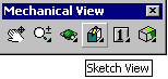
Make your view planar to the sketch plane using the SKETCH VIEW Command from the Mechanical view toolbar (or use AMVIEW Enter S(ketch View) Enter or 9 Enter at the Command line if you prefer).
Sketch (but do not Profile just yet) the geometry as shown on the new workplane.

Now use the AMSPLITLINE command.

This solves the profile like a normal sketch and you can add the constraints required as normal. Solve for your fully constrained sketch.
With hindsight and for the dimensions of the block we are soon to specify it is best that the bottom of the profile is about one to one and a half inches above the work axis line as shown in the second pic furthur down.
If you have to move the profile up then make sure Ortho is ON, type MOVE (or M) Enter grab it by holding down the the left mouse button and slide it up until it looks about right.
(I eventually came back and removed the Fix constraint and placed a dimension of 1 inch between the bottom of the SplitLine1 (thats the profiles name in the browser) and WorkAxis1. Rememember this dimension lays on the sloping WorkPlane2. The problem was the tip of the projected FaceSplit1 was hanging over the end of the base of the block on the XY plane and could not be profiled. After updating I found it still just over hung the end so to vary the plot I edited workPlane1 reducing it from 75 degrees to 70 degrees.)
Next (without changing views), place your sketch plane on the other horizontal XY WorkPlane1 which should be visible and accept the defaults (use AMSKPLN or click on the New Sketch Plane button on the Part Modeling toolbar shown below).
Your UCS Icon should indicate the change. Now draw a rectangle (shown in Red below) to encompass your existing profile and make sure it goes lower than the work axis.
That was interesting, remember the Sketch Plane we are sketching the rectangle on is on the World XY plane so our rectangle top is about 5 inches further away from the observer (you) than the bottom. Realize the 'vertical red rectangle' above is really the bottom profile sketch on the XY plane in the next pic down prior to being profiled and then extruded up in the Z direction to form the block.
Now run the AMPROFILE command and select the new (shown as the red) rectangle. You don't need to constrain this, so go ahead and extrude (AMEXTRUDE or g) this by the amount we want our main extrusion to be. In our case the value is 3.
Lets look at what we have done in an isometric view. Choose RightFrontIsometricView from the Sketch View button flyout on the Mechanical View toolbar (the one already referred to above). If that's too hard just enter 8 at the Command line. Here is my own effort doing the tut.
You will probably notice two things:-
1. the orientation of the model is not exactly the same as the pic below. That is because ORBIT was probably used to dynamically roll it around into a position that pleased operator. You can play with ORBIT if you like but if you loose it just hit 8 to get back to the right front iso view and, if you want hit = Enter it will go more into the orientation shown. If you get greedy and do an = Enter twice you will have to hit - Enter to get back (for completeness note that [ Enter and ] Enter roll the image around to the left and to the right respectively.) If you must play with this now remember 8 Enter followed by = Enter will get you back into position to carry on with this tutorial.
2.The second thing you will have noticed is the yellow/gold shading of the block (our PART1_1). We could live without it but if you want to practice it here goes. Right click on PART1_1 in the browser the slide down to 'Properties' then out to 'Color' and left click. The Select Color window opens and you can select a color and press "OK' or you could just type 40 (say) in the 'Color' box and press 'OK' (if you were working to a color standard).
The color thing is not over yet. To get the color fill effect we have to 'shade' the model. Real operators do this sort of thing to improve understanding not appearance. Giving buttons and the command line a miss go to the Menu and press View->Shade->Gouraud Shaded and there you are. To get back press View->Shade->2DWire Frame but you can leave it shaded for the time being.
Next run the AMFACESPLIT command (Part->Sketched Features->FaceSplit) as shown below and choose the "pRoject" command line option and select the bottom face of the block we had created as the face to split.

Turn off shading and you will see the pattern engraved onto the bottom of the block as shown below.
Mind you when I turn off my shading after allocating color the wire frame and profile projected onto the XY plane are retain the although the gold color was lost a bit in the process of making the gif in my expensive image processing system (MS Paint!) and its a barely seeable yellow.
To tell the truth my projected sketch on the XY plane (it's not really a profile in MDT speak until we 'Profile" it (thats profile with a capitol P) actually hung over the end so it could not have been profiled. There was two options. One was to expand the FaceSplit1 in the browser and double click on SplitLine1 to initiate editing to allow me to MOVE it down a tad (I eventually drove it down with a dimension down to the WorkPlane1 of one inch) or double click on WorkPlane2 and edit the 75 degree to a lower angle. I did that too setting it at 70 degrees.
*** here is where it went wrong for me! ***
a) when I do the read AmProfile below and pick on the FaceSplit1 (on the bottom face of the block) it just says 1 Found 1 filtered out and it wont profile
b} Esc'ing out from trying to amprofile and selecting theFaceSplit1 in the browser causes the whole four bottom edges of the block and the FaceSplit1 to show dashed selection lines.
c)MDT4 and MDT6 Help give no example of using a closed splitline although it is is described as being either a line or closed loop. After trying one more time with a simple cube ie putting the closed splitline on the top and amfacesplit onto the base and getting exactly the same failure on amprofile I accepted there was no sketch projected or otherwise to profile and have gave up here.
*** YES! It was me! It works fine if you do the extra inial Enter when you issue the AMPROFILE command (I've drawn attention to the instruction line below -AJ ***
Next you will invoke the AMPROFILE command as such.. (You should zoom in on the profile first to make selection easier)
Command: AMPROFILE
Select objects for sketch: <press return here> *** Do this extra Enter before you start picking! -AJ ***
Select part edge to close the profile: <select an edge of our projected pattern>
Select part edge to close the profile: <repeat until all 9 edges are selected & highlighted>
Select part edge to close the profile: <press return>
Solved fully constrained sketch.
Computing ...
Now we perform our main extrusion of our profile. Extrude the profile, Intersecting, through the part. The desired result is shown below.

Now to test it out, we can double click on workplane2 in the browser and adjust our projection angle to be smaller than 75 degrees. I have shown it below with an angle of 45 degrees.

o0o