This is not an "As Designed" function of MDT but yes it can be done, but it requires a little trickery. As I'm sure you have already discovered, MDT does allow for Mirroring a part using AMMIRROR, however the new mirrored part is not parametrically linked to the source part as it makes a entirely new part definition from it., hence changes to the source part are not reflected in the mirrored 1/2.
The solution seems simple enough, you just want an instance of the same part with a Z scale of "-ve" 1 (-1). Attempting to use any of AutoCAD's native mirror functions like "Mirror" & "3DMirror" will result in a message indicating that you must use "AMMIRROR" to mirror parts, but that's not what your after, is it.
The solution is this. (I have tested this with MDT 4 and it works well)
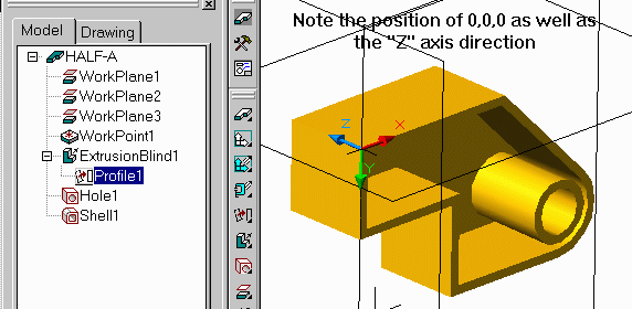
1. Make the part you want as a file. Lets call it "Half-A" for this example. In this example I have made it a single part file but that doesn't necessarily have to be the case. Now save that file as "Half-A". It is advisable that this part has been created so that a shared point with it's future second half is at 0,0,0 to make things simpler later. In my example I made the 3 base workplanes to keep things organized. I then turned off visibility of those workplanes so an not to confuse things later. Once saved, close the file.
Note: Remeber to turn off workplane visibility before saving, else you will get very confused when assembling.
2. Start a new blank MDT file (In my case I used a Part file but an Assy file can work too). Now you've been told before not to use XREFS so continue at your own risk. First off, make the 3 base workplanes so you can see your 0,0,0 as well as introducing "true" MDT items to the drawing which will be required at the next stage for assembling.
Issue the XREF command and attach the file "Half-A", however upon inserting, supply a "Z" scale value of "-ve" 1 (-1). Place the part at 0,0,0. Finally save this file as "Half-B". You will notice in the Browser that there is no Part with features listed as seen below, just the workplanes will be listed. Once saved Close the file.
Note: Do not save this file with the workplanes visibilty off, they are needed at the next stage.

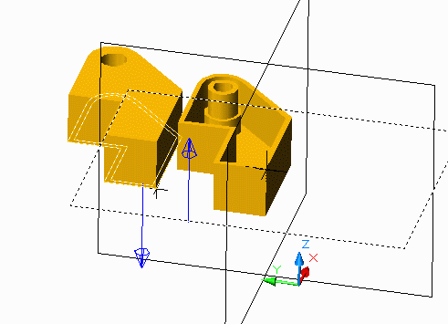
3. Start a new Assy Drawing. and then using catalog (AMCATALOG) instance
one instance each of "Half-A" and "Half-B". Now assemble the 2 parts together
using features from "Half-A" and workplanes from "Half-B". In the picture
below, "Half-A" is on the left side and its face is being mated with the
workplane from "Half-B".
Note: You cannot localize the parts A or B as that will cut the dependancy and cause it to no longer work.
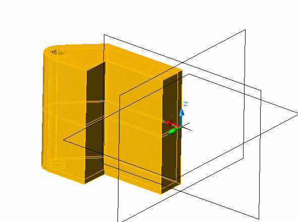
Your two-halves assembly is complete!
To test that it works as expected, in MDT 4, double click on the "Half-A" in the browser and add a feature or something. Please note that all editing MUST be done on Half-A since it is the only "real" MDT part. As you do so you can see that "Half-B" is updating real-time with "Half-A".. Once your done editing the part and you return to the assembly level, accept to save your changes to the external file. In the example below, I edited the extrusion depth (doubled it), lengthened the part and re-ordered the hole to occur after the shell as well as changing the hole to be drilled rather than counter bored, and upon updating the part the 2nd half updated immediately to reflect the changes in both halves.
And more importantly, drawing views CAN be created form this configuration. Enjoy!
o0o