
Figure 1: A simple truss structure.
By Bill Fane
One of the many interesting tools in the Mechanical Desktop® Power Pack is the FEA (finite-element analysis) functionality. You can use it to perform load, stress, and strain analyses on a part.
This tutorial will not be a full lesson in stress analysis. It assumes you already have a working knowledge of this topic. What you will learn is how to use the FEA tools in Mechanical Desktop software to perform stress analysis operations on Mechanical Desktop parts.


Figure 1: A simple truss structure.
Let’s begin with a bit of background theory.
Calculating the loads in the members of a simple truss structure is relatively easy (see Figure 1). That calculation is really just basic Statics 101.


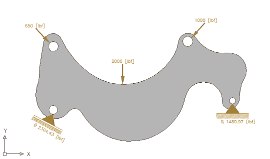
Figure 2: A complex part, subject to multiple loads.
On the other hand, doing a stress analysis on a complex solid link subject to multiple loads and anchorages could get a little messier (see Figure 2). In fact, it is probably impossible, or at least extremely difficult, to analyze such a structure using traditional manual methods.


Figure 3: The part represented as a finite-element mesh.
On the other hand (wait a minute; how many hands is that?), what if you replaced the solid link with a bridgelike truss consisting of a great many thin members like the structure shown in Figure 3? The math for solving this problem is quite simple; it just takes a whole lot of time if you perform the calculations manually.
Getting Started
Luckily, you don’t have to do that. Your Mechanical Desktop software can perform thousands of calculations in a few seconds. So replacing the continuous, homogeneous part with a mesh of small finite-sized elements, which you can then analyze very easily with the FEA tools in the software, is a quite viable option.
The Power Pack option of Mechanical Desktop includes both 2D and 3D FEA tools. We start this tutorial with a simple 2D example, using many of the default settings that come with the software. Next month in part 2 of this tutorial we will look at some of the other 2D options and, finally, consider more complex 3D designs.
1. Start Mechanical Desktop from the Power Pack icon on your desktop.
2. Start a new drawing (in English units) using the Start from Scratch option.
3. Start the Rectangle command by selecting Design > Rectangle from the main menu.
4. Pick a suitable starting point, then enter @10,1 at the Command: prompt.
Beam Me Up... This rectangle represents the front view of a simple rectangular beam. Now you are going to apply loads and supports to it.


Figure 4: The FEA 2D?Calculation dialog box.
1. From the main menu, select Content 3D > 2D to switch the software into 2D analysis mode. The menu bar changes to show Content 2D.
2. Select Content 2D > Calculations > FEA… to start the AMFEA2D command.
3. Pick a point inside the rectangle, which opens the FEA 2D—Calculation dialog box (see Figure 4).
4. Enter 1 in the Thickn. d = text box on the Default pane.
5. On the Loads and Supports pane, click the Individual Force button. The FEA 2D—Calculation dialog box closes, and you are prompted to specify an insertion point.
6. Using an object snap, pick the midpoint of the top line of the rectangle.
7. Press the Enter key to accept the default value of 1000 pounds.
8. Press Enter again to accept the default rotation angle. The dialog box reopens.
9. On the Loads and Supports section, click the Fixed Support button. The dialog box again closes, and you are prompted to specify an insertion point.
10. Using an object snap, pick the intersection point of the lower-left corner of the rectangle.
11. Press Enter to accept the default rotation angle. The dialog box reopens.
12. On the Loads and Supports pane, click the Movable Support button. The dialog box closes, and you are prompted to specify an intersection point.
13. Using an object snap, pick the intersection point of the lower-right corner of the rectangle.


Figure 5: A simple beam with loads and supports applied
14. Enter –90 as the rotation angle. The FEA 2D—Calculation dialog box reappears.
15. Drag it off to one side so you can see your drawing, which should now resemble Figure 5.
I Feel Stressed...
Now that you have applied the load and supports to the beam, you are ready to do the stress analysis.
1. Drag the FEA 2D—Calculation dialog box back on screen.
2. In the upper-left corner of the Results pane, click the Isolines and Isoareas button. The FEA 2D—Isolines (Isoareas) dialog box opens (see Figure 6).

Figure 6: The FEA 2D?Isolines (Isoareas) dialog box.
3. On the Graphic Representation pane, click the Isoareas button and then click OK. The FEA 2D Isolines (Isoareas) and FEA 2D—Calculation dialog boxes close. The software works for a moment and then prompts you to specify a base point.
4. Press the Enter key to accept the default.


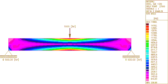
Figure 7: The results of the FEA stress calculation.
5. When you are prompted to specify an insertion point, pick a point to the lower right of the beam.
6. Left-click or press Enter to return to the FEA 2D—Calculation dialog box.
7. Click Close in the FEA 2D—Calculation dialog box. Your drawing should look like Figure 7.
Analyze This... Congratulations! You just completed your first FEA stress analysis. Now you must analyze the results and if necessary, redesign the structure.
Let’s start the analysis by looking at the beam and its accompanying table (see Figure 7). The table maps to a series of color regions, and numbers appear beside each of the mounting points to indicate the load each is carrying.
Look at the table more closely. Starting from the top down, it shows:Look at the last item (the color bar) first. At first glance, it appears that each color corresponds to a different stress range, from the very low light magenta through to the very high dark red. The red zone is obviously a danger area.
A second glance reveals several subtleties, however. The most significant point to note is that by default the software assigns colors based on the highest calculated stress value and then divides that value into 24 equal ranges. If you reduce the load by half (500 pounds), then the color zones on the beam and the colors in the table remain unchanged, but the stress levels beside each color swatch in the table are reduced by half. To really understand the stresses in the part, you must compare the highest stress value with the yield point for the material.
The next point to note is that the stress values are all positive because von Mises stresses do not indicate tension or compression.
And Now for the Fine Print… Let’s start with a direct quote, copied and pasted from the Mechanical Desktop Help facility:
“The FEA tool is very basic and is not intended for full FEA analysis. For example, this FEA tool does not consider dynamic loads or temperature influences on materials. The FEA tool is intended to provide an engineer, who is familiar with FEA, a general idea of where the areas of strength and weakness reside. However, for a complete and final analysis, a full FEA package should be used.”
I would go one step further and suggest that nothing will ever replace a real-world test on an actual part. Never base life-critical design decisions solely on FEA. (True! FEA gets your design closer to the mark before you commence the more expensive prototyping and physical testing phase saving time, money and frustration -aj.)
Be sure to come back next time when we delve further into the wonderful world of FEA, including a look at some of the other 2D options and perhaps even a bit of 3D analysis.
And in Conclusion... FEA functionality in Mechanical Desktop software can be a very useful tool for designers. It should never replace a full FEA analysis and/or a physical test, but it points out possible problem areas so that you can rework a design to improve the odds that it passes formal testing.
o0o