
Knuckle
Avoid parametric pitfalls with these smart modeling tips
What could possibly go wrong?
by Bill Fane
A bit of forethought makes all the difference between a merely adequate parametric part model and a truly elegant one. The real power of parametric models comes from the fact that they are parametric and hence can easily be changed. However, if you overlook a few minor details when you create a model, you may find it almost impossible to change later.
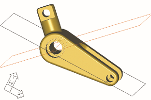
Consider the part shown in figure 1. We will run step-by-step through a quick modeling sequence, and then I'll point out possible pitfalls and a few tricks. The obvious place to start is with the front profile, which consists of two arcs and two lines. Dimension, constrain, and extrude them to create the base feature. While you are here, you might as well add the fillets around the two edges and place the two holes.
|
|
| Figure 1. Our first pass at designing this part creates a few problems that don't show up until we try to change it. |
The central slot wants to be perpendicular to the line of centers between the two arcs, but the part has no suitable flat surface to use as the sketch plane. No problem ..simply add the black work plane.
Now sketch on the work plane, select the sketch as the profile, constrain and dimension it, and cut extrude the slot.
Once again, the part presents no suitable flat surface for the sketch required by the round peg. You will need to add the red work plane at an angle to the lineof centers. To place the work plane, you first need to create the red work axis on the counterbored hole.
As expected, you need to sketch, profile, constrain, and dimension the circle required to make the peg. You can add the filleting to the end of the peg and to the junction between the peg and the large arc.
Fortunately, you can use the end face of the peg as the next sketch plane, so you don't need to create a work plane. Sketch, profile, constrain, and dimension suitable profiles and then cut extrude to form the flats on the side of the peg. Finally, poke the hole through the peg and you are done.
What could possibly go wrong?
Oops, the extrusion for the round peg partially blocks the counterbored hole, as shown in figure 2. We should have placed the hole after we extruded the peg so it would trim the lower bit off the peg. Fortunately, Mechanical
Desktop lets you rearrange the sequence in which features were created. Use your mouse to grab the hole in the feature browser and drag it down until it is below the peg extrusion, as shown in figure 3.
 |
| Figure 2. The extrusion for the round peg partially blocks the counterbored hole. We should have placed the hole after we extruded the peg so it would trim the lower bit off the peg. |
 |
| Figure 3. To fix the peg problem in figure 2, grab the hole in the feature browser and drag it down until it is below the peg extrusion. |
Houston, we have a problem. The browser will not let us drag the hole any further down than it already is. I guess we will have to delete the hole and place a new one.
Now what's wrong? When we try to delete the hole, Mechanical Desktop also wants to take out the entire part except for the first base extrusion. The slot, the peg, the flats and hole on the peg—all gone.
We have just committed one of the most common errors in creating and constraining features. We created the red angled work plane for the circle profile for the peg, but in turn we had to place that work plane on a work axis. When we created the red work axis, Mechanical Desktop asked for a circular feature, so we selected the counterbored hole.
The problem is that the red axis is now dependent on the counterbored hole, and the red work plane is dependent on the axis, and the peg profile is dependent on the red work plane, so the profile is dependent on the counterbored hole. This means that the peg cannot exist until the hole does, so you can't relocate the hole below the peg in the browser.
Not only that, you can't even edit the type of hole to change it from a counterbore to a countersink or a simple drilled hole.
This sequential dependency also explains why most of the part disappears when you delete the counterbored hole.
So what is the cure? You have two choices: place a second hole concentric with the counterbore to trim the bottom of the peg, which is potentially messy, or delete the counterbored hole and rebuild the part properly.
What constitutes properly?
To begin with, you should generally attach work features as high up the browser tree as possible. Also attach them to significant details that are not likely to ever go away. When placing the red work axis in our example, we should have selected the large radius of the base profile rather than the counterbored hole.
When we do so, we can move the hole up and down the tree and edit its type as desired because nothing else is dependent on it.
The same rule applies for the same reasons when you constrain a later sketch back to an existing feature.
This leads us to the next rule, which states that filleting and chamfers should generally be the last features you apply to a part. There are two reasons for this. Fillets and chamfers require a lot of computation and can drastically slow down the processing of a complex part. They can also conceal a detail needed to comply with the previous rule.
In our sample part, if the fillets exist before we place the counterbored hole and the red work axis, they attach to the fillet at the tangency line between it and the face of the part. Once again, if you try to delete the fillet, say to replace it with a chamfer, you also take out everything downstream that is dependent on it.
Fortunately, if you did break the rule and apply the fillet first, you can always suppress it. Right-click on it in the browser and select Suppress. It goes away, and the sharp edge returns. Place and constrain to the sharp edge, and then unsuppress the fillet to bring it back.
Let's make a change to the part. Edit the main body extrusion by increasing the large radius.
A problem immediately becomes apparent, as shown in the isometric section view in figure 4. The slot no longer goes all the way through.
This leads us to the final rule. You should avoid dimensioning, constraining, and extruding to fixed values if that does not reflect the design intent.
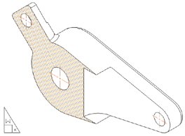 |
| Figure 4. This isometric view highlights another problem—the slot no longer goes all the way through the part |
Let's look at the slot. Create its sketch on the black work plane, which is defined as on axis/on axis through the red and black work axes. Create a tombstone shape that you then constrain and dimension.
Now we come to the problem of the extrusion amount for the slot. Because it's a midplane extrusion, you can't cut through but must give it a value. If you give it a fixed value that is less than the diameter of the large radius on the main body, or increase the body radius, the slot no longer goes through.
Simple solution: use a formula for the extrusion amount. It should be twice the radius of the body arc, as specified by the parameter name (d1, d2, etc.) of the radius. If we do it this way, the total extrusion depth is always equal to or larger than the height of the part, so the slot always goes all the way through.
As you have seen, you can easily build a parametric part that is fully constrained, looks right, but is nearly useless. The good news is that it is usually even easier to do it right.
That's amazing! In one short article you showed us all there is to know about good modeling techniques.
Not quite. Be sure to come back next time when we investigate several clever techniques for ensuring that a part remains symmetrical.