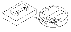
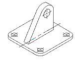
Close Edge When creating a sketch and the lines and arcs would fall on top of existing edges you can use these edges to define the sketch. Draw the sketch so its edges will fall within the pick box size to an existing edge of the part. Draw a sketch on a sketch plane of a part, issue the AMPROFILE command, select the sketch, ENTER and then when prompted " Select edge to close profile ": select the edge(s) to close the profile. Dimension the new profile to the part. Then extrude or revolve the profile as normal. This new feature can not be arrayed or copied. | |
![]() |
![]() |
Copy Edge If you only want to copy selected edges use the AMPARTEDGE command. These copied edges can be profiled to create features or new parts. |
Appending Objects to a Sketch In Mechanical Desktop 3.0 you can now add or remove objects from the sketch. If the profile was extruded, revolved or swept you will need to return to the sketch. Then add or remove objects from the sketch. Maintain the same rules for this sketch as any other sketch. Then issue the AMRSOLVESK command (Append option) in the Part Modeling toolbar or right click in on the profile name in the browser. Then select the new objects and add dimensions or constraints as needed. If the profile was extruded, revolved or swept, you will need to update the part for the change to take affect. You can erase the entire sketch and replace it with a new object(s). If there are other features that were consumed by the new objects they will be regenerated once the part is updated but will not be constrained to the new feature set. |
Copy Sketch When there exists a feature that has a sketch that you would like to use instead of redrawing and constraining a new sketch, use the AMCOPYSKETCH command with the Feature option. First, make the face that you want to place this copied sketch to the active sketch plane. Then issue the AMCOPYSKETCH command, type "F" and ENTER to copy the sketch of a feature, then select a point to locate the sketch. All of the dimensions on the sketch will also be copied. The XY locating dimensions or constraints will not be copied. The sketch can be copied from one part to another. This sketch can then be extruded or revolved. |
![]() |
Copy Feature In the same manner that a sketch was copied, you can use the AMCOPYFEAT command to copy features. Make the face that the feature will be placed on the active sketch plane, issue the AMCOPYFEAT command, select the feature to copy. It does not need to be on the same part. Then select a point on the sketch plane to place the feature. To locate the copied feature, edit the sketch and place dimension and constraints. |
Silhouette Edge to Close Sketch (As in the first tip above ..) A silhouette edge can also be used to close a sketch. Before profiling the sketch change the variable DISPSILH to 1 and change the current sketch view. Then profile the sketch and then select the silhouette edge of the part to close the sketch. When done change the DISPSILH variable back to 0. This will improve performance. |
![]() ![]() ![]() |
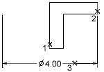
Diameter Dimensions for Rotated Parts When creating cylindrical parts by rotating the sketch there is an option in the AMPARDIM command for creating diameter dimensions. Create the sketch, issue the AMPARDIM command, select the line that the part will be rotated about, select the second edge to dimension to, pick a point for the dimension then type "D" and ENTER to create a diameter dimension. This dimension will show up in the drawing views. |
![]() |
Ordinate Dimensions To create an ordinate dimension, first select near the point on the sketch that you want to be the zero point and then select a location point. A linear dimension will appear. Then press O and then press ENTER. The dimension will change to an ordinate dimension with a value of zero. Any dimension placed after that will be an ordinate dimension related to the zero dimension. If placing an ordinate dimension based on a different zero dimension than which the last ordinate dimension was based on, select its extension line for the first selection and then pick the point to dimension. You will need to place a separate zero ordinate dimension in both the X and the Y directions. |
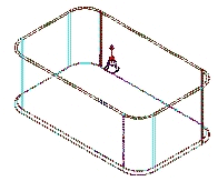
Face Draft In Mechanical Desktop 2.0 shelling was added that allowed for thin walled parts. With shelling, the faces were offset and parallel to the original face. Now with face draft you can change the shelled faces so that they have a different angle. A face draft can be applied to shelled parts or any particular face. A split line can be used for the edge to base the face draft from. After a face exists on a part, you can apply a face draft. Issue the AMFACEDRAFT command from the Part Modeling toolbar or right click in the browser and select Face Draft from the pop up menu header name Place Features. A Face Draft dialog box will appear. Make any changes in the dialog box as necessary and then select a draft plane and then select the faces to draft. A cone shaped icon will appear in the middle of the draft plane as shown in Figure 12. This icon is showing that the face(s) below the plane will draft outward and the face(s) above the plane will draft inward as the cone represents. The face draft is a feature and can be edited and deleted. Adjacent faces can have different draft angles. |
![]() |
Resolve Profiles In Mechanical Desktop 3.0 you can now resolve a sketch to find out how many dimensions or constraints are required to fully constrain it. Issue the AMRSOLVESK command (Solve sketch option) in the Part Modeling toolbar or right click in on the profile name in the browser and select Re-Solve profile. The command line will read "Solved under constrained sketch requiring "??" dimensions or constraints". |
Automatic Dimensioning for Drawing Views In Mechanical Desktop 3.0 there is an unsupported command called AMDIMV that will automate the placement of reference dimensions in drawing views by creating multiple dimensions with limited picks. It will automatically dimension to the endpoints and center points of the selected objects. There are five dimension styles to choose from: baseline, linear, stacked linear, or ordinate. Issue the command, select in the view that you want to dimension, then select the objects that you want dimensioned by using any AutoCAD technique and ENTER. From the command line, select the style to use and then select a direction for the dimensions to go by selecting a point with the mouse. The base point will show up as a blue circle. To change the base point, type "P" at the command line and select another point using object snaps. When the dimensions look correct on the screen, ENTER to exit the command. It will not dimension to endpoints of lines that are collinear to one another. It will dimension to the first endpoint only. The properties the dimensions take on are from the current dimension style. |
Dimensioning an Ellipse To dimension an ellipse, select the ellipse and then use the quadrant snap and select a quadrant and place the dimension. Repeat the procedure for the other side. Figure 7 shows a dimensioned ellipse and the selected quadrants. |
![]() |
Right Mouse Click If in doubt where to find a command, right mouse click on the name in the browser. The majority of the appropriate commands will be available. |
![]() |
Construction Lines Construction geometry can be used to dimension to quadrants of arcs as well as reduce the number of constraints required to constrain a sketch. The following illustrations show a construction line that is tangent to the top of the arc and a construction circle that has a hexagon that is projected onto the circle. Note in Mechanical Desktop 3.0 there is a command for creating construction lines and circles. | |
![]() |
![]() |
Visibility of Parts and Objects The AMVISIBLE command can be a helpful command for hiding Mechanical Desktop parts as well as AutoCAD objects. Note that if a drawing that has parts or objects hidden is opened with regular AutoCAD the hidden parts or objects will not be visible nor is there a way to unhide them in regular AutoCAD. |
Xvalue and Yvalue Constraints In Mechanical Desktop 3.0 you can now use the Xvalue and the Yvalue to constraint to the endpoint of lines. Issue the AMADDCON command with either the XValue or Yvalue option in the Part Modeling toolbar. Then select near the endpoint of the line you want, or select an arc or circle you want a second line, arc, or circle lined up with. Then select the second line, arc, or circle |
Equal Constraints A new 2D constraint is the equal length constraint. With this constraint, you can make two line segments equal in length. Issue the AMADDCON command with Equal Length option in the Part Modeling toolbar and select the line that the second line length will be equal to. Then select a line to be equal in length to the first. When dimensioning the profile, either line segment can be dimensioned, but they both can not be dimensioned. Otherwise, you would over constrain the sketch. When one of the dimensions value changes for a line that has an equal length constraint applied to it, the length of the second line will also change. Dimensions can be placed before or after the constraints are applied. |
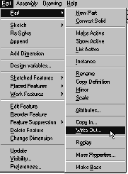
Writing Out a Part If you want to write out a Mechanical Desktop part and do not want to externalize it, you can use the AMPARTOUT command as shown below ***AJ -Note AmPartOut is replaced from MDT4 on with AMCOPYOUT (see the companion AMCOPYIN). This is the way to create (write out) a file from your current drawing (or bring in a copy of a file in). For years I just externalised out (making an Xref) or Xrefed in then 'localised' severing the connection. Bit clunky but I never thought too much about it because it seemed to be the method that flowed from the AMCATALOG command for interfacing with other files.*** (*So the screenshot needs repacing amending but this wording is still valid for AmCopyOut -AJ*) You will be prompted for a file name and location. This new file has no relationship back to the originating file. Note: Do not use the WBLOCK command, as it will write out all the parts in the file not just the selected part. |
![]() |
Rotating Parts When creating Mechanical Desktop parts they may be in a different orientation than you prefer. Use the AutoCAD command ROTATE3D to rotate a part(s) about an axis. Updating All Parts |
Checking for Part Corruption To make sure that a part is not corrupt, issue the AMSANITYCHECK command and select the part to check. Flip to the text screen and if the part is corrupt, you will get a paragraph of letters and numbers that will not be legible. If the part is corrupt you can use the AMREPLAY command and recreate the part stopping the part before the corruption occurs. You can also look in the browser for features that are red and delete them. If the part is in good condition, you will see a text string like the following: ![]() ![]() ![]() ![]() ![]() ![]() ![]() ![]() |
Apply Materials to Parts for Dynamic Rotation When shading parts with the AccelView you can apply a material to them instead of using the color of the block. From the Render toolbar select Materials and then select Materials Library or issue the RMAT command. Select a material and import it into the Materials List. Select OK to return to the Materials dialog box. Select the material and attach it to the part. Then from the Desktop View toolbar select Set 3D Graphics and check Apply materials. Shade the part. It should take on the appearance of the attached material. Note: texture maps (textures that get their appearance from a TGA file) do not work for shading. Render Icon |
Base Isometric View To create a base view that is an isometric view, orientate the part or assembly to the viewpoint that you want to appear in the isometric view. If it is an assembly and a scene does not exist, create one. Then generate a base view with active part or scene option, then when prompted for the orientation, type "V" to use the current view orientation. Centerlines and Centermarks in Isometric Views |
![]() |
Automatic Dimensioning In Mechanical Desktop 3.0, there is an unsupported command called AMDIM. This command will automate the dimensioning of AutoCAD 2D objects by creating multiple dimensions with limited picks. It will automatically dimension to the endpoints and center points of the selected objects. The dimensions are fully associative 2D dimensions. It will work on lines, polylines and objects that have been profiled (polylines will only be dimensioned to end points). There are five dimension styles to choose from: baseline, linear, stacked linear, or ordinate. Issue the command, select the objects using any AutoCAD technique to dimension and ENTER. From the command line, select the style to use and then select a direction for the dimensions to go by selecting a point with the mouse. The base point will show up as a blue circle. To change the base point, type "P" at the command line and select another point using object snaps. When the dimensions look correct on the screen, ENTER to exit the command. It will not dimension to endpoints of lines that are collinear to one another, it will dimension to the first endpoint only. The properties the dimensions take on are from the current dimension style. If they are AutoCAD objects that have been dimensioned with the AMDIM command, you can profile the objects and the dimensions. If an object(s) have already been profiled, issue the AMDIM command and then reprofile the object(s) and the dimensions. |
Feature Suppression Feature suppression adds new functionality by allowing features to be hidden in a part but without deleting them. Feature suppression is like freezing the objects on a layer. Feature suppression can be used to simplify parts, show them in different states through the manufacturing process, create different parts or to reach faces and edges that otherwise you would not be able to get to. For example, if you wanted to dimension to the theoretical intersection of an edge that was filleted you could suppress the fillet and add the dimension and then unsuppress the fillet. Once a feature has been suppressed it can be unsuppressed by selecting unsuppress. If a feature that is suppressed has a feature that is dependent upon it and you right click on the feature in the browser, you will have two options. Unsuppress, will unsuppress the selected feature. Unsuppress + will unsuppress the selected feature and any feature that is dependent to it. For example, a hole that was created concentric to a fillet would be dependent on the fillet. When a feature is suppressed its icon in the browser will be grayed out and a circle and hidden line will go from the browser to the feature name. There are three ways to activate feature suppression and unsuppression:
|
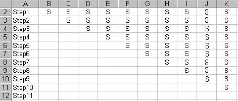
Table-Driven Suppression Features can now be suppressed though an Excel spreadsheet. Design variables can still be driven from the table. Before suppressing features through a table, a part must exist that contains features. It may also have design variables but it is not required. Feature suppression through a table can only be done for the active part. Issue the AMVARS command in the Part Modeling toolbar or right click in the browser and select Design Variables. Make the Active Part tab current and click Setup from the Table Driven section of the dialog box. A table Driven Setup dialog box will appear. There are three type of table driven parts.
|
![]() |
o0o