Surfaces and Solids
John Wilson
Flying Through Space
Unlike 2D work in which you invariably look straight down on the World Coordinate System's xy plane, you use a variety of viewing directions when you construct 3D models. Consequently, to work efficiently in 3D space you need to be able to set a viewing direction with a minimum amount of effort. In order to confidently work in 3D space, you need to know exactly what you are looking at-that is, whether you are looking toward the front of your model, toward the back, and so forth.
Also, you'll use a variety of viewing modes as you construct your models. You'll work in the wireframe mode, in which surfaces are transparent, when you want to select edges and modify or add objects on the far side of your model. You'll use the hidden-line mode, in which surfaces are opaque, to better visualize your model and when working on its near side. When you need an even more realistic depiction of your model, you'll work in a shaded mode in which surfaces are colored-in according to their object color. Shaded modes are also useful in verifying that surfaces and shapes of your model are as you intend them to be.
AutoCAD developers have had trouble establishing both viewing directions and viewing modes as the software has developed into a 3D modeler. Their first attempt, the VPOINT command, requires you to imagine a view direction in space, and then to specify the angles of that view direction. This command also tried a real-time method, involving a compass and an axis tripod for setting a view direction that is-I can say without exaggeration-worthless. A second attempt was made with the introduction of the DVIEW command. This command offers real-time viewpoint establishment, but the image of your model flickers so severely that it's almost impossible to tell what you are looking at. Moreover, the hidden-line viewing mode is not compatible with the real-time options of the ZOOM and PAN commands.
With AutoCAD 2000, though, Autodesk seems to have finally got it right with the introduction of 3DORBIT and a set of related commands for establishing views in real-time. For most models the operation is smooth, and you can readily visualize your model. To further help, AutoCAD 2000 also introduced a new shading command, SHADEMODE, that offers a variety of viewing modes that work with 3DORBIT. Mechanical Desktop also depends on 3DORBIT to dynamically set view directions, and even Inventor uses a 3DORBIT-type technique for establishing view directions.
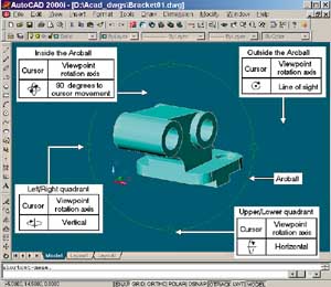 |
| Figure 1. The 3DORBIT command displays a green circle, called the arcball, in the center of the current viewport. As you move your pointing device, the screen image of your model rotates about an axis that passes through the center of the archball, and the orientation of that axis depends on the location of the screen cursor. |
The 3DORBIT command is so easy and intuitive to use that you don't need to know much about the command to make good use of it. However, it is more flexible and complex than it first appears to be, so we will take a closer look at it and its related commands in this column. We will also look at the extra options and parameters that the Mechanical Desktop version of 3DORBIT offers.
The Arcball
When you start 3DORBIT, a large green circle, called the arcball, appears in the center of the current viewport. As you move your pointing
device while holding its pick button down, the image of the model rotates about an axis that passes through the center of the arcball and the orientation of that axis depends on the location of the screen cursor, as described in the following paragraphs and shown in Figure 1. Also, the appearance of the screen cursor changes to indicate the rotation axis-orientation.
When the screen cursor is within the arcball, it assumes the shape of a small sphere encircled by horizontal and vertical oval-shaped arrows. When you depress the pick button of your pointing device, the viewpoint rotates around an axis perpendicular to your movement of the screen cursor. For instance, if you move the cursor down and to the right 30 degrees relative to the horizontal edges of the
viewport, the view rotation axis is inclined 60 degrees relative to the horizontal edges.
When the cursor is outside the arcball, the screen cursor changes to a dot encircled by an arc-shaped arrow, and the model rotates about the viewport's line of sight as you move your pointing device with its pick button held down.
When you move the screen cursor within either of the small circles on the top and bottom quadrants of the arcball, the screen cursor assumes the form of a horizontal line within a vertical oval-shaped arrow, and the view rotation axis is horizontal when you move your pointing device while the pick button is depressed.
When you hold down the pick button of your pointing device as the screen cursor is within either of the small circles on the right and left quadrants of the arcball, the screen cursor becomes a vertical line within a horizontal oval-shaped arrow, and the view rotation axis is vertical.
If, when trying to set a viewing direction, your model appears to spin about in space in an uncontrolled manner, you might try using just the arcball quadrants to establish a view. Use the top or bottom quadrant to set a viewing direction from the horizontal plane, and then use the right or left quadrant to set a viewing direction within the plane.
Hidden-line and shaded viewing modes are supported while setting viewing directions in real time, but depending on the complexity of the model and your computer's speed and memory, images may degrade from shaded to hidden-line to wireframe to bounding-box representations. If you have selected objects prior to initiating 3DORBIT, only the selected objects will be displayed, which may improve dynamic viewing. Also, you can turn off degradation. To do this, start the OPTIONS command, select the Systems tab, and then click the Current 3D Graphics Display Properties button to open the 3D Graphics System Configuration dialog box. In this dialog box, clear the Adaptive Degradation checkbox.
Autodesk Inventor also uses an arcball-like method for dynamically setting view directions. The three ways to initiate this action are to select Rotate from the View menu, select the Rotate the Model button from the Standard toolbar, or simply hold down the F4 key. A large circle that has a short line extending from each quadrant is displayed in the current window. Viewpoint direction rotation works the same as it does in AutoCAD (with the short lines replacing the small circles), and even the appearances of the screen cursor is similar. You can pan as you are rotating the viewing direction by clicking somewhere in the window. Inventor pans the view so that the point you picked is moved to the center of the circle (and window).
Shortcut Menu Options
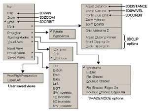 |
| Figure 2. 3DORBIT's right-click shortcut menus offer numerous options that affect your view of your model. |
Once you have started 3DORBIT, you can right-click your pointing device to bring up shortcut menus that offer numerous options that affect the view of your model. Many of these options start other commands, and you will probably find that it is more convenient to initiate those commands through these shortcut menus than it is to invoke them directly. These menus are shown in Figure 2 and are described as follows.
Exit ends the 3DORBIT command. You can also end the command by pressing the Enter or Esc keys.
Pan invokes the 3DPAN command for dynamically moving the image of your model without changing its size. Unlike the real-time version of the PAN command, 3DPAN works in hidden-line and perspective viewing modes.
Zoom initiates 3DZOOM for dynamically increasing or decreasing the apparent size of your model, even in hidden-line and perspective viewing modes.
Using Materials in Shaded ViewsIn both AutoCAD and Mechanical Desktop you can apply a rendering material to 3D surface and solid objects; that material is used in SHADEMODE's four shaded viewing modes and in 3DORBIT's real-time operations. Three steps are required to utilize a rendering material: you must enable material display, you must create a material, and you must apply that material. To enable the material display, invoke the OPTIONS command, select the System tab, and click the Current 3D Graphics Display Properties button. This button opens a dialog box titled 3D Graphics System Configuration. Here you select Render Options and then select Enable Materials. If you want to incorporate a bitmap pattern with the material, also select Enable Textures. Materials with bitmap patterns can simulate such things as wood grain, bricks, and floor tile, but you are not likely to use such a material when your objective is to improve 3D visualization while constructing a model rather than to create a life-like rendering of a finished model. To create a material, start the RMAT command to display the Materials dialog box. Make certain that Standard is displayed in the list box on the right side of the Materials dialog box, and click the button labeled New to open the New Standard Material dialog box. Enter a name for the new material. On the left side of the dialog box is a list of the material properties, or attributes, that you can control. For working with shaded viewing modes, you will probably need to set only the Color/Pattern and the Transparency attributes. Click the Color/Pattern radio button to set your material's general color. By default, material uses the AutoCAD object color. If you want your material to have a different color, clear the By ACI checkbox and then specify red, green, and blue values to set its color. To set the material's relative transparency, click the Transparency radio button and specify a transparency value. A value of zero makes the material completely opaque, while a value of one makes the material completely transparent (and invisible).
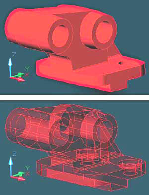
Once you have set the material's properties, click the OK button of the New Standard Material dialog box to return to the Materials dialog box. Make certain that the name of your material is highlighted in the Materials list box. You next need to use one of three methods to assign the material to one or more objects. If you want to assign the material to specific objects, click the Attach button and then pick the objects that are to assume the material's properties. If you want to assign the material to all objects that use a particular AutoCAD color, click the By ACI button and then select a color number from a displayed list. To use the third method for attaching a material, click the By Layer button and select a layer name from the displayed list. All objects in that layer will assume the material's properties. Using a semitransparent material is especially useful when you are constructing solid models. The slightly shaded surfaces help you visualize your model's geometry, yet no part of the model is hidden, and you can see and select virtually any edge. Figure 3 shows two versions of SHADEMODE's Gouraud Shaded Plus Edges mode with an AutoCAD solid model that has an attached material. In the top panel of the figure, materials are not enabled while they are enabled in the bottom panel. The material uses the object color, and has a transparency value of 0.67. Although such a material is not as attractive as the default opaque mode, it is easier to work with. Transparency works only when SHADEMODE's Gouraud Shaded Plus Edges or Flat Plus Edges viewing modes are in effect. |
Orbit returns from another operation to real-time view direction rotation.
More opens a submenu with the following options:
- Adjust Distance initiates 3DDISTANCE, which dynamically moves the camera in perspective views along the line of sight. The effect is similar to changing the focal length of a camera's zoom lens.
- Swivel Camera invokes the 3DSWIVEL command for rotating the viewpoint about a fixed point. The effect is as if you were looking through the viewfinder of a camera on a tripod. When you swivel the camera to the right, objects in the viewfinder shift to the left; when you swivel the camera upward, objects appear to shift downward.
- Continuous Orbit continually rotates the viewpoint in 3D space. After you select this option, depress the pick button of your pointing device, drag the screen cursor in the direction you want the viewpoint to rotate, and then release the pick button. The rate of rotation is proportional to the speed you used when moving the cursor. Press the pick button to stop the rotation.
- Zoom Window allows you to define a specific rectangular area you want the view to focus on.
- Zoom Extents zooms in or out as necessary to display and fit the entire model within the current viewport.
- Orbit Maintains Z locks the current orientation of the z axis as you rotate the viewing direction with 3DORBIT. This option, which was introduced in AutoCAD 2000i, is especially useful in architectural models to keep walls and such upright.
-
Clipping Plane options clipping planes are two invisible planes spaced along and perpendicular to the current line of sight. When activated, the front clipping plane hides everything in front of it (toward the camera), while the back clipping plane hides everything behind it (away from the camera). Clipping planes are most often used in setting up architectural interior views because they effectively remove walls and other viewing hindrances. When you select the Adjust Clipping Planes option, a small window opens that has a view perpendicular to the current viewport's line of sight. It shows the front clipping plane as a white horizontal line and the back clipping plane as a green horizontal line, as shown in Figure 4. You can drag these clipping planes along the line of sight, and the results are displayed in real time in the current viewport of the AutoCAD graphics area.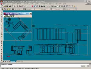
Figure 4. 3DORBIT's Adjust Clipping Planes option opens a small window having a view perpendicular to the current viewports line of site. In this window, the back clipping plane as a white line. As you drag these clipping planes along the line of site,you can observe the results in AutoCAD graphics area.
Projection opens a menu for toggling between the parallel and perspective viewing modes. A check mark indicates which mode is current.
Shading Modes opens a menu for setting any of the SHADEMODE command's viewing modes, except 2D wireframe.
Visual Aids opens a menu for turning AutoCAD's compass, grid, and UCS icon on and off. The compass is a set of three mutually perpendicular rings composed of tic-marks-which fit within the arcball-that help you visualize angles in the three principal-coordinate-system planes-the xy plane, the yz plane, and the zx plane. The compass may help you remain oriented as you set viewing directions in real time.
Reset View restores the view that was current when the 3DORBIT operation started.
Preset Views opens a menu for setting one of the six standard orthographic views or one of the four isometric views that look down toward the xy plane. The views are based on the World Coordinate System.
Saved Views opens a secondary menu that lists all user-saved views; however, it is available only if one or more user-saved (with the VIEW command) views exist. Click a view name to restore it.
Mechanical Desktop Viewing Operations
Basically, 3DORBIT works the same in Mechanical Desktop as it does in AutoCAD, but it has a few enhancements. For one thing, surfaces are semitransparent in shaded-with-edges-displayed viewing modes. This is useful when you are selecting edges for fillets, chamfers, and so forth that are on the far side of your model. In AutoCAD, on the other hand, surfaces in all shaded modes are completely opaque. Also, Mechanical Desktop has two commands that specify the center of the view-direction-rotation axis and then invoke 3DORBIT. These commands are helpful when the current view is zoomed-in to an extremity of a large model. One of these command, AMROTCENTER, finds the geometric center of the model within the current viewing direction, pans to center that point in the current viewport, and starts 3DORBIT. The other command, AMSELROT, prompts you to select a point. Mechanical Desktop pans so that the point is centered in the viewport, and starts 3DORBIT.
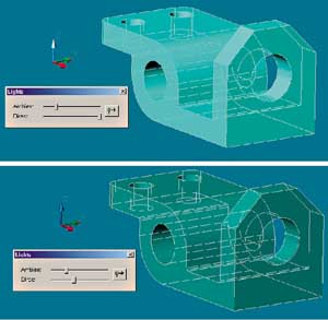 |
| Figure 5. You can set the relative amounts of ambient and direct light in shaded views in Mechanical Desktop. The top panel in this figure shows the effects of the default settings. In the bottom panel, direct light has been reduced to make the model more transparent. |
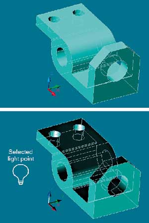 |
| Figure 6. Mechanical Desktop's AMLIGHTDIR command controls the apparent location and direction of the light source in shaded views. The top panel in this figure shows the default light direction, while the bottom panel shows the results from picking the point indicated as the light source. |
Mechanical Desktop also has two commands for controlling lighting properties in shaded views. AMLIGHT displays a dialog box that has slider bars for controlling the relative amounts of ambient light and direct light. By default, ambient light is low and direct light is high. As you increase ambient light, shaded objects become brighter and more opaque; as you decrease direct light, objects become darker and more transparent and different surfaces acquire the same relative brightness, as shown in Figure 5.
The second command, AMLIGHTDIR, controls the apparent location of the light source in shaded views. By default, shaded views are illuminated by a single direct light located to the left and above the viewport's line of sight. One of the several ways to start the AMLIGHTDIR command is to select the light bulb icon in AMLIGHT's dialog box. You will be prompted to select a point location for the light, and the new light direction will immediately take effect. An example of a user-selected light location is shown in Figure 6. The changes you make with AMLIGHT and AMLIGHTDIR affect just the current drawing, and only for the current session.
John Wilson, who runs a design and drafting service in St. Louis Park, MN, is the author of the newly published CMP book titled Mechanical Desktop 5: Parametric Modeling available at www.books.mfi.com/auto/AC3718.html. Contact him at jewilson.slp@worldnet.att.net.