|
Interactive
Project - MDT Non-Parametric Solids
|
You will need Mechanical Desktop for this project.Open the drawing called 2D_3D.DWG (Zipped). This drawing contains two 2D views of a rocker arm. 1. Select Parts>Preferences - Uncheck "Apply Constraint Rules" Box.
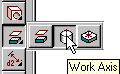
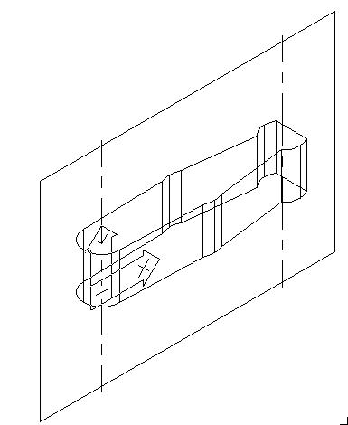
2. Profile Right View - AMPROFILE 3. Extrude Profile - AMEXTRUDE - Blind - 1.25 distance, no taper. 4. Block Left View - BLOCK - Select all objects in left view. Make insertion point the lower right end-point. 5. Create Work Axis - AMWORKAXIS - select cylindrical edges on both ends.
6. Create Work
Plane- AMWORKPLN - On Edge/Axis - On Edge/Axis - Create Sketch Plane
7. Set Sketch Plane View - 9 (enter) 8. Insert Side Profile - DDINSERT - Scale = 1,Rotation = -90 and Explode.
9. Profile Side (Left) View - AMPROFILE (Tip: Use "Window" to select.) 10. Set DISPSILH to 1. Regenerate (RR). 11. Add Parametric Dimensions - AMPARDIM - Dimension as shown below.
12. Set to SW Iso View. (Accelerator Key - 8) 13. Extrude Profile
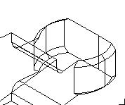
- AMEXTRUDE - Midplane - Dist = 1.25 - Interfere. 14. Chamfer - AMCHAMFER - Equal Dist to 0.06, select 4 curved ends as shown. 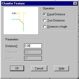 .
. 
15. Hide Work Plane and Work Axis - Right Click on features in Browser and turn off visibility.
16. Part is complete. |