
Figure 1. Blind terminations can cause gaps when you change more basic features.
CADENCE August 2000 Third Dimension article by John Wilson
| Table 1. Termination Options by 3D Feature Type | ||||
| Termination | Etruded | Revolved | Swept | Lofted |
| Blind | Yes | No | No | No |
| Through | Yes | No | No | No |
| Mid-Through | Yes | No | No | No |
| By Angle | No | Yes | No | No |
| MidPlane | Yes | Yes | No | No |
| Path Only | No | No | Yes | No |
| To-Face/Plane | Yes | Yes | No | No |
| From-To | Yes | Yes | Yes | Yes |
| Sections | No | No | No | Yes |
| To-Face | No | No | No | Yes |
All Mechanical Desktop 3D parts are made from sketched features, and all sketched features are made from 2D outlines (or profiles). You can use any one of the following four methods to transform these 2D profiles into a 3D feature:
After creating the first sketched feature, subsequent features interact with existing features through the Boolean join, cut and intersect operations to make geometry that is more complex than a single feature can be. (Beginning with Release 3, Mechanical Desktop also has an operation-named Split-that is a combination of cut and intersect operations.) To give you additional control over a feature's geometry, the commands that create them have a variety of options for establishing the end-or termination-of the feature. You can, for example, stop a sweep feature when it meets an existing face, rather than stopping it at the end of its path. And in making an extrusion, you can push the profile in both directions from its original position, rather than pushing it in just a single direction.
Mechanical Desktop has a total of 10 different options for establishing feature terminations. However, any sketched feature type does not have all 10 termination options. For instance, the command for making a swept feature offers only three termination options. Table 1 shows you which termination options are available for each of the four sketched feature types.
The options that use existing geometry to terminate a feature are often preferable to those that end it on a set point (based on a distance or angle) because the feature will change as the more basic (or parent) features change. For example, if an extruded, dependent feature terminates on a specified face, it will become longer or shorter whenever the face is changed or moved. On the other hand, when you extrude the dependent feature's profile for a certain distance (a Blind termination), a gap may appear when you lengthen the base feature, as shown on the right in Figure 1.
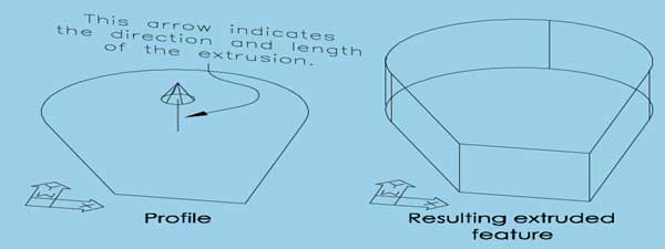
Blind. Blind terminations are only available for extruded features. The profile is pushed in one direction for the length specified in the Distance edit box of the Extrusion dialog box. As you set up the extrusion, an arrow anchored in the geometric center of the profile points in the extrusion direction, and its length indicates the extrusion distance, as shown in Figure 2. You can reverse the extrusion direction with the Flip button of the Extrusion dialog box.
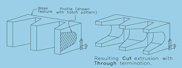
Through.The Through termination option is available only for cut, intersect and split operations on extrusions. As shown in Figure 3, it causes the extruded profile to pass through all existing features in the extrusion direction. Mechanical Desktop indicates the extrusion direction with an arrow on the profile. Select the Flip button of the Extrusion dialog box to reverse the direction.
Mid-Through. You can only use the Mid-Through termination with cut, intersect and split operations of extruded dependent features. Extrude the profile in both directions through all existing features, as shown in Figure 4.

By Angle. By Angle terminations are available only for revolved features. Revolve the profile in one direction by the angle entered in the Angle edit box of the Revolution dialog box. An arrow on the profile indicates the revolution direction. You can click the Flip button in the Revolution dialog box to reverse its direction.
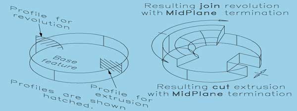
MidPlane. You can use MidPlane terminations with both extruded and revolved features. In making a revolved feature, the profile revolves in both directions for a total angle equal to the value entered in the Revolution dialog box's Angle edit box; for an extruded feature, the profile moves in both directions from its original position for a total distance equal to the value in the Distance edit box of the Extrusion dialog box. Figure 5 shows an example of a MidPlane termination for both a revolved and extruded feature.
Path Only. Path Only terminations, which are available only for sweep features, push the profile from the start of the path to the end of the path, as shown in Figure 6.

To-Face/Plane. The To-Face/Plane termination option is actually for two different types of terminations-a Face termination and a Plane termination. This termination option is not available when the profile has multiple loops. A command-line prompt will ask you to select an object. If you select either a work plane or a planar (flat) face on a 3D feature, Mechanical Desktop will issue prompts relating to a plane termination type. If you select a non-planar face, a face termination will be used.
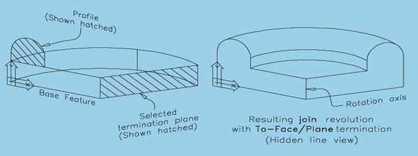
Plane terminations are based on a plane that extends in an infinite distance in all directions. When you select a work plane, no additional prompts are issued and the feature will terminate on that plane. On the other hand, when you select a planar face on a 3D feature, Mechanical Desktop asks you to specify whether the face represents a face or a plane. When you specify that it is a plane, the profile you want to extrude, revolve or sweep does not have to actually intersect the face you selected. Figure 7 shows an example of a Plane termination.
Mechanical Desktop uses a Face termination when you select a nonplanar face and specify that you want.use a selected planar face as a face rather than as a plane. Unlike with Plane terminations, the profile must completely intersect the face as it travels in its specified direction through space. If any part of the profile extends beyond the face due to size or location, the operation will fail. Take a look at Figure 8 for an example of a Face termination.

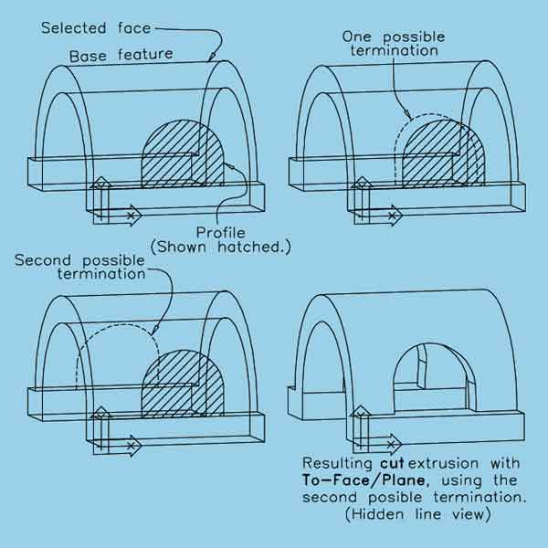
If the face you select is curved to the extent that more than one termination is possible, Mechanical Desktop will display the possible terminations and issue command-line prompts so you can select the one you want, as shown in Figure 9.
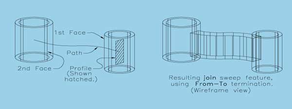
From-To. The From-To termination option establishes both ends of a feature. The 3D feature will begin at the surface of one face or plane and end at a second face or plane. The requirements for the two faces or planes, as well as the steps in selecting them, are the same as for the To-Face/Plane termination. The profile sketch can be located between the two faces or planes or, as shown in Figure 10, behind one of them. When the profile has multiple loops, the From-To termination option is not available.
Sections. The Sections termination option is specific to lofted features. The 3D feature will begin on the first specified profile and end on the last specified profile.
To-Face The To-Face termination option is unique to lofted features. It causes a lofted feature to end on the selected face of a 3D feature. The face does not have to be planar, but it does have to be within the sections that you want to loft; that is, it can't be in back of the first or beyond the last section. You can also select a work plane as the termination face.
John Wilson is president of Computer Based Drafting in St. Louis Park, MN.
Contact him at jewilson.slp@worldnet.att.net