MDT Quilts
note links are for record only. All the Quilt information is extracted here.
www.cadonline.com/reviews/software/cad/1099adsk/mdt.htm (Bill Fane MDT 4 article).
For those of you who use complex surfaces, or would like to, Mechanical Desktop 4 contains a great many improvements. These include the ability to stitch several NURBS surfaces together into a single quilt that you can then use to create a parametrically editable and constrainable solid. If you import less precise data from other surface modelers, Mechanical Desktop 4 can heal them into a usable surface quilt. You can now attach an xref toolbody part even if you started the current part drawing in “single-part” mode. This should prove to be a real boon to the tooling and moldmaking industries.
www.cadalyst.com/reviews/software/cad/0301mdesktop/mdesktop.htm (Bill Fane MDT 5 article).
If you use surface modeling at all, you will be pleased with Mechanical Desktop 5's new and improved features. They fall into two categories: a group of functions to analyze, edit, stitch, and repair surface models, and a single function that lets you take a single, open-face surface or quilt and thicken it into a standard Mechanical Desktop solid part of any specified thickness.
www.cadconceptsinc.com/mdt4.htm
Easily merge surfaces together to form parametric solid-model "quilts," cut other surfaces with them, detect and heal imperfect faces and edges, and convert C0 surfaces into quilts.
www.cadenceweb.com/newsletter/mcad/0700_2.html
Surface modeling has been enhanced, as it is now possible to stitch a series of surfaces into what Mechanical Desktop calls a "quilt surface or into solid models . Surfaces can also be edited by dragging, while the software maintains the proper continuity. Version 5 also allows surfaces to be thickened in order to create a solid and fillets can now be applied across multiple surfaces.
www.pro-des.com/iges.htm
IGES file transfer is one of the most popular ways to get 3D model data from a CAD program or solid modeler into a CAM program such as Cimatron or Mastercam. To create an accurate cavity and core image in a mold we must have an IGES file that will import into the CAM system without errors or unmerged surfaces.
By default Pro/Engineer colors all interior edges of an IGES or surface quilt
IGES export to CAM systems can also be improved if the exporting system is set to an accuracy setting that is compatible with the CAM system that will be importing the file.
www.cadalyst.com/features/0703cadcam
Even if you ignore all the other benefits (see additional reading), the ability to fabricate parts based solely on a 3D model file is a compelling reason to venture into solid/surface modeling. Of course, there are always limitations. One major issue is the exchange of 3D model files. 3D modeling applications use various mathematical engines called geometry kernels to define their 3D file formats. The ideal setup for exchanging files between CAD and CAM occurs when the applications use the same data file format, thereby eliminating translation issues. Unfortunately, that isn't always practical in our heterogeneous CAD/CAM software environment where others in the workflow process use applications that differ from yours.
All of the CAD data in the world is created by about two handfuls of proprietary and licensed geometry kernels. Three mainstream avenues help you get your data from the CAD to the CAM system:
- Native file formats
- IGES (an industry standard)
- STEP (a newer industry standard)

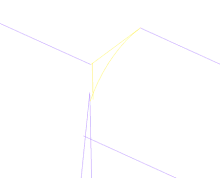
Figure 1. The yellow edge shows that two surface edges in the domed area are not knitted together properly. Zooming in shows the problem area more clearly. This problem occurred because of mismatched tolerances between the CAD and CAM software packages.
|
Whether done explicitly or via a background process, each can pose problems. Failures are akin to a stitched quilt that's been ripped apart. The quilt in this case is a "watertight" group of surfaces that represents the exterior shell of your model (figure 1). Disparate tolerances between packages can be tuned, but this takes time and can be hit or miss. Some systems require you to make these settings prior to the creation of geometry-that is, changing the setting won't rebuild the existing model geometry to the higher/lower tolerance. This can be a problem if you don't know who is going to be making your parts.
Regardless of whether the geometry was created at an "inferior" tolerance or the translation process has corrupted it, the CAM software you are considering should definitely provide some sort of geometry healing tools to repair the data. How extensive, useful, and automated they are may or may not be important to your company. If you deal with data from several different CAD packages and many different suppliers, this will be of vital interest to you. If you create all of your geometry in-house, with a single CAD program, translations may not be an issue at all (Figure 2).

|

|
Figure 2. The yellow edges represent an unintentional hole created in a solid model during translation. On the right you can see the corrected vertex. The ability to repair imported geometry efficiently can make a big difference in productivity.
|
www.cadalyst.com/features/1001vendors/stepiges.htm


