CADENCE October 2000 Third Dimension
John Wilson
Explosive Scenes

Figure 1. Exploded view drawings are commonly used to show all
of the parts in an assembly and their spatial relationships to each other.
|

Figure 2. Explosion factors establish the spacing between individual parts. They rely on assembly constraints that are based on planes.
|

Figure 3. Unlike explosion factors, tweaks are not dependent on assembly constraints. You can use them to -move individual parts or subassemblies in any direction.
|

Figure 4. Assembly trails,
which indicate the explosion factor and tweak movements of an assembly's parts,
help viewers understand the spatial relationships of parts.
|
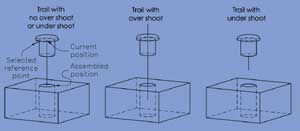
Figure 5. Over and under
shoots lengthen or shorten a trail. They are based on the current position of a
user selected reference point on an exploded or tweaked part and the assembled,
or constrained, position of that reference point. |
In manufacturing industries, exploded view drawings, such as the one shown in
Figure 1, are used extensively in assembly and service manuals because they
clearly show the individual parts of an assembly and how they are spatially
related. You make exploded view drawings in Autodesk's Mechanical Desktop by,
almost literally, exploding the assembly -the parts become spread apart in space.
Then, just as you can with an individual part, you can make drawings from the
exploded assembly.
Exploded assemblies are referred to as scenes in Mechanical Desktop, and they are
created within a special mode: the Scene mode. (Mechanical Desktop scenes have no
relationship with AutoCAD rendering scenes, which are for defining a particular
view and set of rendering lights.) Working in Scene mode is similar to working in
Model mode. The distance between parts is controlled by an explosion factor. You
can also tweak the distance between parts and even move them sideways and rotate
them. Moreover, to more clearly indicate how parts go together, you can connect
them with lines that are called trails.
Explosion Factors
You create a scene by selecting the Scene option of the AMNEW command. (As I
typically do in this column, I'll use command names rather than toolbar button or
menu option names in describing how to initiate operations because they are more
basic.) Mechanical Desktop will prompt for the scene's name, with SCENE1 as the
default name, and for an overall explosion factor. Then, you will be asked if you
want to activate the scene. If you respond positively, Mechanical Desktop will
switch to its Scene mode and activate the scene. If you choose to not immediately
activate the scene, you can later invoke the AMACTIVATE command and select the
Scene option. You can also have multiple scenes and use AMACTIVATE to move from
one scene to another.
The new scene will initially use the Model mode viewpoint, and the parts will be
spaced apart according to the scene's explosion factor. Explosion factors rely on
assembly constraints that involve opposing planes. For instance, the two planes
specified for an insert assembly constraint will move away from each other by the
value of the explosion factor, as shown in Figure 2. Movement is always away from
the grounded part of the assembly or subassembly. The units for explosion factors
are those of the assembly. Thus, when the parts of an assembly are based on
millimeters, an explosion factor of 1 represents 1 mm.
You assign explosion factors with the AMXFACTOR command. This command offers you
the option of having the explosion factor apply to all parts in the scene or to a
specific part. When you select a part (which is done by picking a point on it)
that is a member of a subassembly, Mechanical Desktop will ask if you want the
explosion factor to apply to the entire subassembly or to just the selected
part.
Applying explosion factors is a straightforward process. Generally you will
assign an overall explosion factor when you create a scene, then set a viewpoint
that best shows the exploded assembly, and lastly modify the explosion factor of
individual parts to accommodate the part size and the viewpoint.
Tweaks
Scenes based solely on explosion factors seldom have all of the display
characteristics you desire. Components, whether they are subassemblies or
individual parts, might be hidden or not properly aligned; and they might not
even respond to explosion factors because their assembly constraints are either
not based on planes or offset one another.
You can remedy these problems with the AMTWEAK command. This command enables you
to move and even rotate selected components within a scene in any direction,
without regard to their assembly constraints. When you invoke AMTWEAK from the
command line, you will be prompted to select a part. As with AMXFACTOR, if the
part you pick belongs to a subassembly you can specify that you want to select
the entire subassembly or just the part that was picked. Once you have specified
the component you want to tweak, Mechanical Desktop displays a dialog box that
has three radio buttons for you to use in choosing one of three tweak options:
Move, Rotate or Transform.
Move
The Move option of AMTWEAK moves the selected component linearly by a specified
distance. You will be prompted from the command line to select an object that
defines a line. You can select a straight edge or the round edge of a cylindrical
or conical feature on a part. When you select a round edge, the axis of the
feature defines the move direction. The object you select does not have to be on
the part you want to tweak. An arrow pointing in the move direction will appear,
and you will be prompted to enter the move distance. If you want to move the
component in the opposite direction of the arrow, enter a negative number.
Rotate
The Rotate option rotates the selected component about an axis. As with the Move
option, you will be prompted to select an object that defines a line. The object
you select will serve as the axis of rotation. You can select a straight edge or
a round edge on any part to define the axis. An arc-shaped arrow will encircle
the axis to indicate the rotation direction, and you will be prompted to enter
the number of degrees you want the selected component to rotate. You must enter a
positive number.
Transform
While the Transform option of AMTWEAK performs the same move and rotate
operations as the other two options, it gives you more choices in specifying
directions and axes. Also, you can perform any number of moves and rotations
until you exit the option. When you select Transform, Mechanical Desktop will
issue command-line prompts for you to either (1) move the selected component; (2)
rotate it; or (3) exit the option (and thereby end the command). When you choose
Transform's Move option, Mechanical Desktop displays the command-line prompt:
Specify start point or [Viewdir/Wire/X/Y/Z]:
If you specify a point using any AutoCAD method, it serves as one end of a
directional line (or vector), and you will be prompted to specify a point for the
line's other end. The x, y and z options move the component in the direction of
those User Coordinate System (UCS) axes directions, and the Viewdir option moves
the component in the current viewport's line-of-sight direction. The Wire option
uses an existing wireframe object to define the tweak's move direction and
prompts you to select an object. The object can be an AutoCAD line, polyline,
arc, circle or ellipse. When you select a polyline that has multiple segments,
the segment the object pick point is in is used to establish the move direction.
When you select a circle, an arc or an ellipse, the move direction is
perpendicular to the object's plane.
If you specified a line for the move direction by either picking two points or an
AutoCAD line or linear polyline segment, the line will also be used to establish
the move distance. Otherwise, Mechanical Desktop will issue a command-line prompt
for the move distance. An arrow indicating the move direction will appear, and
you can either accept or flip the arrow's direction.
When you choose Transform's Rotate option, Mechanical Desktop will ask you to
pick a point to serve as the center of rotation. Next, you will be prompted to
specify the direction of the rotation axis. Your choices are the UCS x, y, or z
axes directions, the current viewport's line-of-sight direction and the direction
defined by a wireframe object. An arc-shaped arrow will encircle the axis to
indicate the positive rotation direction, and you can accept or reverse it.
Lastly, you will be prompted to enter the rotation angle.
After you have performed a move or rotate operation, the Transform prompt for
selecting an option reappears. Select the Exit option to end both Transform and
AMTWEAK. Figure 3 shows an example of a tweak.
You can't edit tweaks; you can only delete them. This is done through the
AMDELTWEAKS command, which issues a command-line prompt for you to select one
component. All of that component's tweaks will be deleted, and it will return to
its pre-tweaked position.
Assembly Trails
Assembly trails, as shown in Figure 4, are lines that show the paths used in
moving parts away from their assembled positions. You create trails on a
part-by-part basis with the AMTRAIL command. Mechanical Desktop places them in
the AM_TR layer, which has white as its color and CONTINUOUS as its linetype.
Trails follow the paths made by explosion factors and tweaks. They are
parametric, and, therefore, they change as the parts and the positions of the
parts change.
When you initiate AMTRAIL, a command-line prompt will ask you to select a
reference point on a part or subassembly. You must pick a point on the edge of a
face. The trail will extend from the center of circular edges and from the
endpoint of straight and arc-shaped edges.
Once you have selected a reference point, Mechanical Desktop will display the
Trail Offset dialog box for you to use in controlling the relative locations of
the trail's endpoints. It is divided into two clusters of edit boxes. The cluster
labeled Offset at Current Position is for the reference point end of the trail,
while the cluster labeled Offset at Assembled Position is where the reference
point would be if the part had not been exploded or tweaked. By default the trail
starts and ends at these two points. You can, though, specify Over Shoot and
Under Shoot distances for both ends. When you specify an Over Shoot distance, the
trail will extend beyond the reference point location; and when you specify an
under shoot distance, the trail ends before reaching the reference point. Figure
5 shows examples of these options.
Once you have created a trail for a part, you can modify its over and under shoot
values by invoking the AMEDITTRAIL command. This command displays the same Trail
Offsets dialog box that is used by the command for creating trails. You can
remove trails with the AMDELTRAIL command, which will issue a command-line prompt
for you to select the trail you want to delete.
Trails follow tweak movements exactly, which can cause problems if you have used
multiple tweaks in positioning a part. Suppose, for instance, you used AMTWEAK to
move a part 12 units in a particular direction. Then after deciding that that was
too far, you added another tweak to move the part six units back toward its
original position. The part's trail will follow the 12-unit tweak, and then turn
back on itself for another six units.
Managing Scenes
Usually scenes automatically update themselves when changes have occurred. You
can, though, force updates by selecting the Scene option of the AMUPDATE command.
When you have set the explosion factors and tweaks within a scene as you want
them, you can prevent inadvertent changes to them with the AMLOCKSCENE command.
This command displays a command-line prompt with options to either lock or unlock
the active scene. When a scene is locked, you can't add or modify explosion
factors or tweaks. You can, though, create and modify trails.
Occasionally you may want to turn off the visibility of some parts within a
scene. For instance, in an assembly that has numerous pairs of bolts and nuts,
you may want to turn off the visibility of all but one representative pair to
reduce clutter. You can control the visibility of parts, subassemblies and trails
by selecting the Scene tab of AMVISIBLE's dialog box.
You can make a copy of a scene with AMCOPYSCENE. Prompts similar to those used in
creating a new scene are issued for you to establish a name and an overall
explosion factor for the copy. The copy will have all of the original scene's
parts, tweaks and trails. You can also remove an unneeded scene by choosing the
Scene option of the AMDELETE command.
The Scene tab of the Desktop Browser lists the names of all parts within the
existing scenes in the file. Those within inactive scenes, however, will be
grayed out. You can conveniently access the commands related to scenes described
in this column through right-click shortcut menus. These shortcut menus are
especially useful in changing explosion factors and adding tweaks to subassembly
parts. When you select a subassembly name, all of the parts in the subassembly
will move. Conversely, when you select a part's name, only that part will
move.
John Wilson is president of Computer Based Drafting in St. Louis Park, MN.
Contact him at jewilson.slp@worldnet.att.net.