vb/cam for mechanical desktop
Modify this CAM routine to work with your milling tools.
|
Chris Lamrock is a tool and die designer at Northern Machine Tool Company in Muskegon, Michigan. He also runs the company’s CNC department. This article originally appeared in the July 2003 issue of Cadalyst Magazine. |
As CNC (computer numerical control) machines continue to invade our lives, wouldn't it be nice to have a simple, no-cost CAM package that works inside a familiar CAD package? This is what you get with VB/CAM, a small Visual BASIC program that runs in AutoCAD Mechanical Desktop 2.0 or higher to quickly and simply generate 2D and 3D tool paths for CNC mills.
VB/CAM has many uses-from engraving to contour milling to machining pockets. Almost anything you can draw, you can machine. VB/CAM uses 3D polylines in AutoCAD as a foundation for creating the CNC program, a simple point-to-point 3D path that consists of multiple linear G01 G-code moves. To produce curves and arcs, the program simply posts out many very short straight-line moves to approximate the shape. This is common practice in many high-end CAM packages, and it keeps things simple to manage in Visual BASIC.
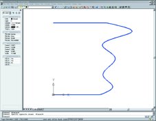
Figure 1. In our example, we want to mill a profile around this shape. |
PREPARE YOUR PATH
Creating a cutter path for VB/CAM is relatively easy. Because the software creates a CNC program that follows your 3D polyline with the bottom and center of the tool, you must take into consideration the diameter, the length, and in some cases the shape of the tool.
Say you want to mill a profile around the shape in figure 1. First you must move the CAD data into a position where the x, y, and z zero positions correspond to a similar point on the workpiece in the mill. We'll call our lower left corner x,y zero and the top of the workpiece z zero. We want to mill this contour around the outside of the shape with a 0.50 diameter flat endmill. The first step is to join all of the wire data into a single polyline. The Amjoin3d command works well for this. If we offset the polyline 0.250 to the outside of the shape, we get a path for the centerline of our tool to follow.
|
Get the Code
Download the code in
the Get the Code area. |
To finish the path, we need to convert the polyline into a 3D polyline. A good way to do this is to create 1.00 tall vertical lead lines at the beginning and ending of the path. Run Amjoin3d again and join the new lead lines to the path. The last thing Amjoin3d asks is
Reverse direction? [Yes/No]
 Figure 2. The first step is to convert the profile to a 3D polyline so VB/CAM can go to work. |
VB/CAM GOES TO WORK
Now you're ready to run VB/CAM. Download the VBCAM.ZIP file from Cadalyst's Get the Code area and unzip it. It contains the VBCAM.DVB file as well as a VBCAM.TXT Help file. Type Vbaload at the Mechanical Desktop Command prompt to load it. The Vbarun command brings up the macros page. To start VB/CAM, select Visual_Basic_ CAM, then click Run.
 Figure 3. VB/CAM presents this dialog box where you enter your tooling parameters. |
Now, fill in the rest of the form. Settings such as the tool number, the spindle rpm, and the approach and cut feed rates must all be configured here for each CNC program you create. The Help file that comes with VB/CAM explains all these boxes in detail. Once you fill in the form, press the Write File button to create the CNC file and write it to your disk. To pick another 3D polyline and start fresh, press the Reset button. To exit VB/CAM, select Exit. You load your finished file into your CNC machine in the usual manner. I highly recommend doing a dry run of everything just to make sure nothing was missed. When everything looks correct in the dry run, let the chips fly!
I created VB/CAM to write programs for our HAAS vertical mills, and some settings are hard-coded in the software. There may be elements of the CNC file that don't work on other CNC machines. Most of these differences appear in the first few and last few lines of the CNC program and should be easy to see. Included in the document file are directions on how to find these areas in the Visual BASIC code and some insight about how to modify it to work for your machines.
VB/CAM is a no-frills, simple-to-use CAM package that can be easily modified to fit many needs. Thanks to Visual BASIC, AutoCAD, and a little elbow grease, maybe the next CNC program you run will come from something as familiar as a 3D polyline.