Cad Tutor Community thread
I want to extrude a shape along a spiral. My problem is how to create the spiral? Thanks, Jim
Jim,
You won't realise how funny this question is unless you've been around here for a while.
I'm definately going to do a tutorial on this one day.
Do you mean a SPIRAL or do you mean a HELIX. It's a common error but it does make all the difference.
Either way, it's not possible to create a true spiral or helix in AutoCAD but you can draw an
approximation. This can be a really tedious process and so it is usually done with a LISP routine.
You'll find such a routine for creating a helix at this topic (Excellent!-aj).
Here's your spiral lisp routine:
www.cadresource.com/library/lispps.html
(Seems to be the standard version still downloadable in the Autodesk link further below (and held by me in in this folder as a local copy that can be downloaded). This one had a comment promo for Cad Warehouse/Caddalog while unzipping. Starts with lots of triple ;;; comment lines with Autodesk disclaimer and author credit (1985) and tells you to use either spiral or cspiral for interactive. -aj)
Spiral - SOLID Modelling
If it's a spiral as in a cylinderical tube that is like a spring. You draw it like it's manufactured.
A 3D polyline drawn about a 3d solid cylinder, with points drawn on the outside at intervals to SNAP onto.
I do this as a lesson with my school kidz after they have drawn a nut and bolt to create a thread type shape.
Helix - SURFACE Modelling
Similar to above draw a cylinder then points at intervals around the cylinder then a 3D polyline. Copy it and move it up a touch. Then copy and scale up the 3D polyline so it's got a larger radius then the other two. Then create a RULE surf (or TAB surf sorry can't remember which one).
Phew !
Anyway they both work. The second one was used by one of my kidz to show a car suspension spring.
Nick www.cadteaching.com
Thanks for that Mr.T
I just had a quick look on the old message board and I came across this:
"The truth is that it can't be done with perfect accuracy since, as you have discovered, you can't extrude along a 3D spline. However, you can extrude along a 3D Polyline. So, providing you can bear to draw a helix using a 3D polyline, it can be done. Obviously, you only have straight line segments to play with so it can never be perfect. It's the kind of thing that lisp routines are written for. In fact, AutoCAD R12 came with a bonus LISP file called 3dspiral.lsp but sadly it is not included with more recent AutoCADs (but I found it at www.ncneel.com and it is accessible from my index page you just came from to get to this page! -aj) However...
You can find one here: www.spaug.org/LISP_Index99.Html Has a 'helix.lsp' written 8/89 by Tony Tanzillo (I downloaded it into this folder as tthelix.lsp. Got to be careful because the file name is the same as the more recently written one by Tony Hotchkiss downloaded from Cadalyst June02 which is the basis of my Cadalyst Helix page. **Also see at this Spaug page the Nov02 Lisp of the Month (stat.zip) for sress analysis work in Autocad. Has dialog box (see the screen shot).** I also downloaded spring.zip and tap.zip (2001-2002 tips of Month) into this folder).
...and here: www.cadresource.com/library/lispdk.html For HELIX.ZIP 3k Draws 3-dimensional, flat, helical coils. (watch 'helix' again) (**note the hex bolt and nut lisps offered just below the helix.zip**)
This link may also help:
www.tenlinks.com/CAD/user...screws.htm (this is not a link -aj)
www.tenlinks.com/CAD/users/autocad/shareware/index.htm (but I found this link which seems a good starting place but I keep getting distracted by other intersting stuff I see and have not completed finding thread stuff yet -aj)
and this...
Think about how it works, Here is an example for you:-
Set your 3d viewport to SE. Use default UCS.
Start pline at 0,0,0 enter, then
@100<0,10 enter, @100<90,10 enter, @100<180,10 enter, @100<270,10 enter,
@100<0,10 enter, @100<90,10 enter, @100<180,10 enter, @100<270,10 enter,
@100<0,10 enter, @100<90,10 enter, @100<180,10 enter, @100<270,10 enter,
Press enter to complete the command. Notice how it looks.
I hope it helps you out to try this little exercise.
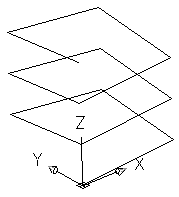
example1.png
(Truth is I could only draw this using LINE or 3DPOLY (in A2002). PLINE would only work on the default (world) xy plane. The Line version looked like you see it above but would not PEDIT to a PLINE. So I used 3DPOLY and drew over it (cheating using OSNAPs) in magenta -aj.)
You can now use the PEDIT command and SPLINE the helix.
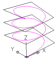
example2.png
(My magenta 3DPOLY ascending set of straight magenta lines (not shown) did respond to the PEDIT and splined to produce the result shown (note contact with original co-ordinates is only at the start and end points -aj.)
Look at this by autolisp code by fuccro and try to figure a scrip from it.
;by fuccuro
;
(defun C:Helix1()
(setq nr 12);segments
(setq fi (/ (* 2 PI) nr) i 0)
(setq r (getreal "Radius of helix "))
(setq p (getreal "elevation "))
(setq old (getvar "osmode"))
(command "3dpoly")
(repeat (+ nr 1) (setq x (* r (sin (* i fi)))
               y (* r (cos (* i fi)))
               z (* i (/ p nr))
       )
       (command (list x y z))
       (setq i (1+ i))
)
(command (list x y (+ z 10)));delete?
(command "")
(setvar "osmode" old)
)
Ok looks to me like:-
given r=D/2 is (mean) radius of coil
given n=nr is number of straight segments per turn
p is elevation or pitch or vertical growth per turn
i (integer?) is count of points so two turns at 30 sements per turn means 60 points
given A=2*Pi/n (where 2*Pi is 360 degrees in radians.
So in Basic speak co-ords are of the form:-
| x | y | z |
| r*sin(i*A) | r*cos(i*A) | i*(p/n) |
One turn or radius 20, pitch 5 using script.
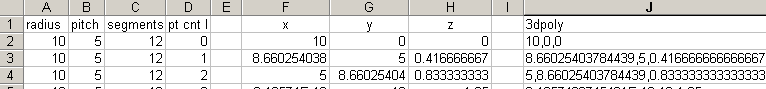
| x | y | z | 3dpoly |
| =A2*COS(D2*2*PI()/C2) | A2*SIN(D2*2*PI()/C2) | =D2*B2/C2 |
=F2&","&G2&","&H2 |
and this...
You can find 3dspiral.lsp here: ftp://195.210.176.221/cad/lisp/3DSPIRAL.LSP
thanks to www.autocad.ru (Russian language site interesting page layout -aj)
...and if anyone knows any more good sources of 3D spiral/helix stuff, post it here and I'll try to pull it all together in a new tutorial.
Dave
There are 2 spiral lisp routines kicking around that I know of. One is for a 2D spiral (sounds like the one you've got) and the other is for a 3D spiral (helix).
The last one is what you want.
usa.autodesk.com/adsk/servlet/ps/dl/item?siteID=123112&id=2525555&linkID=2475161 Autodesk
Their spiral.lsp download is in this folder. The site content is reproduced below:-
How to make a Spiral, Thread or Screw Thread
Published date: 2003-04-04
ID: DL129302
Applies to: AutoCAD® Release 14
adeskftp.autodesk.com/prodsupp/autocad14/patches/spiral.lsp spiral.lsp (4 KB) (not zipped). Use spiral or cspiral.
spiral.lsp (My local copy (not zipped). Execute with spiral or cspiral for interactive -aj.)
First, use an AutoLISP routine such as the attached, spiral.lsp to create the spiral path you need. Then use the EXTRUDE command with a reference object, selecting the spiral as the path.
You can also accomplish this with Mechanical Desktop (MDT) or AutoSurf by using the augmented lines approach. Create a sweep surface using augmented lines as the path. In MDT, use the SURFCUT command to create the solid.