Aussie John
BACK
Line Thickness Tutorial Summary
Task 1: Setup Enviroment (Screen)
TILEMODE _|
1 _|
LIMITS _|
0,0 _|
420,297_|
GRID _|
15 _|
Z(OOM) _|
A(LL) _|
(Note: The grid can be turned on and off with [F7] but leave on)
Task 2: Setup Enviroment (System Variables)
SETVAR _|
UCSICON _|
3 _| (ie the UCS icon ON and at the Origin)
UCSFOLLOW
0 _| (0 ..changing UCS does not effect the view)
(1 ..changing UCS causes a change to the plan view of the new UCS in the current viewport)
MAXACTVP _| (maximum no. of active viewports!)
8 _|
(We make it 8 so the role of maxactvp becomes apparent later!)
Task 3: Commence Drawing
(Use the line command to draw a rectanglular shape)
L(INE) _|
180,100 _| (An absolute location to start off)
@ 125,0 _| (Now relative co-ordinates)
@ 0,75 _|
@ -125,0 _|
C _| (C for Close!)
(Now the rectangle is complete we start the 3D work)
VPOINT _| (-VP is the alias for VPOINT!)
1,1,1 _| (Gives us the NE View)
(Note how it zooms in to fill the screen)
Z _|
0.7x _|
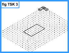 (Notice the view is looking toward the Wcs origin from a position of 1X, 1Y, 1Z hence the 1,1,1 response to the Vpoint command. The Wcs icon is still in its default position as the "w" can be seen on it. The icon was at the lower left of the screen prior to typing Vpoint. All that has changed is the viewing position not the Wcs position.)
UCSICON _|
N _| (..for No origin!)
(Note the Ucs icon relocates itself to the lower LH corner of the screen. This is a useful setting in 3D work generally because as you locate a local Ucs to work on a particular surface you don't have to move it out of the way as it remains in the lower LH corner no matter where you have created the local Ucs.)
UCSICON _|
OR _| (..for ORigin!)
(Places the icons position back in the default position (World) position (so it becomes the Wcs again)
Task 4: Give The Lines Drawn Depth With Line Thickness
(Change the property thickness from zero to 150.)
CHPROP _|
ALL _|
_| (2nd Enter to conclude selection)
T _|
150 _|
_| (2nd Enter to conclude changing properties!)

If we zoom out to display all the screen contents you should obtain a screen image like you see to the right.
Z _|
A _|
Finish with a zoom 0.8x to position the box a little better.
Z _|
0.8x _|
Task 5: Name A View Port
VPOINT _|
1,1,1 _| (Make sure we have the view we want)
(Note how the it zooms in to fill the screen)
Z _|
0.8x _| (About the right zoom factor!)
-V(IEW) _|, (Minus needed for A2000/i/02!)
S _| (..S for Save!)
7 _| (We name the view "7")
Now deliberately change the view
Z _|
Now pick (always use the left button to pick) any two points on the screen.
Ok, now lets restore our view 7.
-V _|, (Using alias only now!)
R _| (..R for Restore!)
7 _| (The view is restored!)
Task 6: Reposition UCS In 3D And Draw The Cross
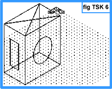
We will draw the cross on top first, the circle second and then construct the rectangle last. The top corner "closest" to you is common for the three faces we intend to draw on so we start off placing the UCS there and will rotate it around onto the faces as required.
UCS _|
N _| (..N for New!)
END _| (turn on endpoint OSNAP)
Pick the top corner "closest" to you.
Ok its on top (notice the W indicating being in the World position is removed).
For the first diagonal line on top.
L _|
END _|
Pick the corner with the UCS on it again.
END > Pick the diagonally oposite corner on the same top face.
_| (Enter to conclude line command)
_| (Enter again to repeat the line command for the opposite diagonal line)
END _|
Pick either remaining corner on the top face.
END _|
Pick the last diagonal corner
_| (Enter to conclude line command!)
Task 7: Draw Circle On Right Face
To do the circle first we need to rotate the UCS onto that face.
UCS _|
N _| (..N for New!)
X _| (to rotate the Ucs about the X-axis, wrapp right hand fingers around the X-axis with thumb pointing in the positive X-direction and the fingers indicate direction of positive rotation)
90 _|
Now a diagonal from the corner where the UCS is down to the opposite bottom corner to locate the midpoint of the face then draw the circle.
L _|
END _|
Pick the top corner "closest" to you.
END _|
Pick the opposite bottom corner.
_| (conclude the line command)
C(IRCLE) _|
MID _|
Pick the mid-point of the diagonal construction line.
30 _|
Task 8: Construct Rectangle on Left Face
There are many ways to do the rectangle but the following steps give an insight to construction methods.
First we will place the UCS on that plane to permit use of the offset command in that plane. Start with the Ucs:-
UCS _|
N _| (..N for New!)
Y _|
90 _|
L _|
MID _|
Pick the line on the base of the left hand narrow face.
MID >_|
Pick the line at the top of the narrow face.
_| (..to terminate line command!)
O(FFSET) _|
25 _|
Pick the vertical line just placed (..to offset)
END _|
Pick an Endpoint in the "+X" direction of the Ucs (i.e. to the right of the Mid points line for the side to offset).
Pick the vertical line again (..to offset)
END > Pick an Endpoint in the "-X" direction of the Ucs in the same plane.
_| (..to terminate offset command)
E(RASE) _|
Pick the vertical line that connects the Midpoints of the top and bottom edges.
_| (..to conclude the erase command)
To create the horizontal lines of the rectangle, starting with a construction line:-
L _|
MID _|
Pick the Midpoint of one of the vertical offset lines.
MID _|
Pick the Midpoint of the other vertical offset line.
_| (..to terminate line command!)
SC(ALE) _|
Pick the two vertical offset lines and the horizontal line connecting them.
_| (..to conclude selection)
MID > Pick the Midpoint of the horizontal line that joins the vertical offset lines for the basepoint.
0.5 _| ( .. the scale factor)
The shape on the vertical narrow face of the box should look like an "H." All that is left to do is connect the ends of the verticals and erase the horizontal that joins the Midpoints of the verticals.
L _|
END _|
Pick a top Endpoint of one of the verticals.
END _|
Pick the top Endpoint of the other vertical.
_| ( ..Enter to conclude)
L _|
END _|
Pick a bottom Endpoint of one of the verticals.
END _|
Pick the bottom Endpoint of the other vertical.
_| ( ..Enter to conclude)
Erase the horizontal line connecting the Midpoints of the verticals:-
E _|
Pick the horizontal line that connects the Mid points of the verticals.
_| ( ..Enter to conclude)
The box should now look like the one in fig TSK 6. Set the Ucs back to the default world co-ordinate system (Wcs) as follows:-
UCS _|
W _| (..Or just hit _| since Wcs is a default)
Task 9: Layout Drawings in PaperSpace
We have created a model in "Model Space" (the X-Y Ucs icon indicates model space). Now we want to create the layouts or what we want to print out on a piece of paper so we go into "Paper Space" (the triangular Ucs icon that appears indicates paper space)
TILEMODE _|
0 _| (..0 for paper space, 1 for model space)
Pick [Cancel] (cancel the dialog box!)
E _|
Pick on the viewport border anywhere (the continous "rectangle" around the image -not the outer dashed one!)
_|
We will make four 4 viewports, one each for a plan, side, top and an isometric view.
MV(IEW) _| (..stands for make viewports in paper space I guess!)
4 _|
Pick a convenient window to occupy the middle of the screen, and make its border equally spaced with the screen edges. Set it to occupy about 3/4 of the screen area (to leave room for borders and title block ect).
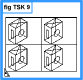
The outcome should correspond to fig TSK 9; four identical images of the model created in tasks 1-8.
The 4 views are probably pictorial (we use the term "isometric" a lot to mean pictorial) . If each view displays something, all is well. Grid visibility at this stage is not important.
Task 10: Show The Four Required Views (Layouts)
The following steps activate the Mviews using the Mspace (Model space) command, then interact with the model using the Vpoint command, and finally de-activate the Mviews using the Pspace (Paper space) command.
MSPACE _|
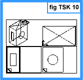
An active Mview ( a viewport in paperspace) is identified by having a thicker or highlighted border.
Note: Image positions are approximate.
The command PSPACE (paper space), de-activates the temporary model environment for the Mview, restoring fully the Tilemode - 0 detailing conditions once more. It is easy to identify when none of the Mviews are active for two reasons.
i) The triangular Ucs icon appears.
i) The thick border is no longer present around one of the viewports.
To carry on:
Commands will act only on the single highlighted window. The next step is to select the top right window to become active and turn it into a plan view so that the face with the cross can be seen. Position the cursor over the top right window and perform a pick within the window. It is now highlighted as active.
VPOINT _|
0,0,1 _|
Front and side projections are also arrived at using the Vpoint command. Creating a projection (Third Angle in this case) means that the bottom right window will be viewed from the Y direction. Pick the bottom right window to highlight it as active.
VPOINT _|
0,1,0 _|
This view also fills the window as much as possible. (Look at the bottom right window in fig TSK 10.) Now pick the lower left window to highlight it as active. For this window, the end view will be viewed from the X direction.
VPOINT _|
1,0,0 _|

This projection also fills the window as much as possible. The screen should now fully match fig TSK 10. Reducing each projection is shown in the next task.
Task 11: Position Views In Viewports
We now have one pictorial and three projection views. Now to change the Zoom so the views are better sized.
Stay in the lower left window.
Z _|
.7x _|
Pick the lower right window to highlight it as active.
Z _|
.7x _|
Pick the top right window to highlight it as active.
Z _|
.7x _|
It can be seen that the top right view isn't to the same scale as the other two views. Zoom it again and choose a value so it looks about right.
Z _|
.6x _|
Some MVIEWS may show grid dots. They can be turned off by highlighting (picking) the offending window(s) and then invoking the command to de-activate the grid. (F7)
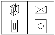
The views are now shown clearly and you can return to Pspace by using the command below. (The Paper space command "Pspace" will de-activate a highlighted Mview window.)
PSPACE _|
Concluding:
These views are not to any particular scale and the projections do not automatically align at this stage. Alignment and scaling would happen in a moment, but this is convenient point for the introductory line thickness tutorial to conclude. However, creating the model and developing the projections in this way is fundamental to working in 3D, even for large assembled designs. It is the underlying method for all 3D work in AutoCAD and LT.
o0o
 (Notice the view is looking toward the Wcs origin from a position of 1X, 1Y, 1Z hence the 1,1,1 response to the Vpoint command. The Wcs icon is still in its default position as the "w" can be seen on it. The icon was at the lower left of the screen prior to typing Vpoint. All that has changed is the viewing position not the Wcs position.)


