Help file
AutoCAD 3D Tutorial
Part 1Basil Harvey
Published in Multi-CAD Magazine
July 1997, pp63

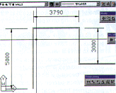
Plan view of a dimensioned kitchen.

DDVPOINT dialogue box

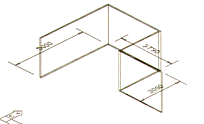
View after using the Elevation command.

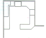
Adding some simple detail to the kitchen.

The Hide command removes hidden lines.
|
AutoCAD in Three Dimensions Part One: "2 1/2 dimensional drawing"
Using AutoCAD to for three-dimensional models is nothing new. Some of the commands that are most useful in 3D have not changed since very early versions of AutoCAD. The
Elevation, Thickness, VPoint and Hide commands that form the basis of this exercise are amongst those that I used in 2.18 (with the advanced drawing extension!), over 10 years
ago. They produce quick results and are a great starting point for understanding a CAD
system that can work with three dimensions.
The aim of this exercise is to produce a very basic axonometric view of a kitchen. To
put this simply, we want a view of a kitchen where we can see at least three faces in
different planes. Perspective views deserve special attention and will be covered in a
later part. Before we begin, it is important to understand what sort of objects we will be
drawing.
I have called the objects drawn here '2 ½-dimensional', as they have very specific
qualities. The only drawing primitive that I will use is the humble Line. I always call
the basic objects such as Lines, 'primitives' as they are the simplest form of object in a
CAD system. When Lines have Thickness applied to them, Lines can be viewed as if they are
three dimensional. It is important to remember, however, that they are not truly
three-dimensional. They are a bit like pieces of paper standing up on their edges. Lines
with Thickness cannot have holes punched through them, nor can they have a different
Thickness at each end. This is why I call them 2 ½-dimensional.
THICKNESS
In the plan view of the kitchen that I have dimensioned here, I have used
the command Thickness before drawing the wall outlines. This has been set to 2400 to suit
the height of a normal wall Thickness determines the height of the Lines in this false,
third dimension. The results of this can be seen in the next step, in which a three 3
dimensional view of the kitchen is achieved.
VPOINT - DDVPOINT
Using the command VPoint allows the user to view the model from a
different direction. A modern version of this command (much later than Version 2.18) is
DDVPoint, which presents a plan viewing circle and a vertical viewing semi-circle. It is
very easy to understand, intuitive and produces quick results. In the dialogue box here, I
have chosen a view from the front right and from 30 degrees above.
The resulting picture can be changed quickly by reinitiating the DDVPoint commands.
PLAN
To get back to the plan view at any time, use the PLAN command and select the option
World. Logically, this will always get back to the 'Plan of the World'.
ELEVATION
Building on the model is easy and can be further enhanced by the use of the Elevation com
mand to set the starting height for the Lines followed by the Thickness to set their
height from that Elevation. I have set up some simple benches using 900 Thickness, a
fridge at 1700 Thickness and put an overhead cupboard starting at Elevation 1300 with a
Thickness of 700. To make it clearer in the 3D view, I have drawn the lines where the
benches touch the walls. In plan, this would be a duplication of the line (This can be
seen in the 3D view).
HIDE
Using the DDVPoint again re veals a much more sophisticated model. The Hide command will
make it even better Remember that these are like bits of paper and there are no actual
tops on the benches yet. AutoCAD tools to Hidden Lines Removed (HLR make this better will
be used in later parts.
ChProp: DDChProp/Change
Oops! Should you forget to set the Thickness of the desired line prior to drawing it,
simply use the DDChProp Corm mand to change the properties. This will allow you to change
Thickness. Unfortunately the only command in AutoCAD that lets you change the Elevation is
the change command. This does not have a dialogue box but allows the Elevation property to
be changed. |
Copyright © 1997 Echo Magazines Pty Ltd. All rights reserved. echomags@echomags.com.au
The Tutorial Command Line Instructions
Notes:
1. Only each entry by the user is shown. Each entry commences on a new line.
2 No Enters are indicated except where a second concluding Enter is required and this is shown on it's own line with a typewriter style "carraige return" symbol _|.
3. The redundant part of the command is bracketed the first time it is used such as in L(INE) for example, and the alias (in this case L), used subsequently.
4. Although commands are traditionally shown in capitals, lower case entry is fine.
LIMITS
0,0
8000, 6000
GRID
250
Z(OOM)
A(LL)
To make a layer "wall" and set it current (or use any other method you prefer).
-LA(YER)
N
wall
S
wall
_| (another Enter to conclude)
Set the line thickness for the wall to 2400
TH(ICKNESS)
2400
Now take your time. Examine each of your command line entries before you press Enter. You can press U for UNDO and your previous entry will be undone but it's better to get it right in the first place.
L(INE)
0, 0 (..start inside left of kitchen wall)
@0, 4000 (..4000 is sufficient, 5000 shown is too much)
@3790, 0
@0, -3000
@600, 0 (..600 is sufficient, another 3790 is too much)
@0, 100 (..start back making wall 100 thick)
@-500, 0
@0, 3000
@-3990, 0
@0, -4100
C (If you had to re-enter the LINE command at some stage then you will need to use @100, 0 to get back to the start point.)
OK, lets save some views..
Z
A (Note how it zooms to fill the screen.)
Z
.8x (That should look better.)
-V(IEW) (Minus needed for A2000/i/02!)
S (..S for Save!)
1 (We name the view "1")
Now we will change to the SE Isometric View
VPOINT (for A2000/i/02 users alias is -VP.)
1, -1, 1
Notice the view is looking toward the Wcs origin from a position of 1X, -1Y, 1Z hence the 1, -1, 1 response to the Vpoint command. The Wcs icon is still in its default position as the "W" can be seen on it.
Lets zoom properly onto this view and save it too.
Z
A
Z
.8x
-V(IEW) _|, (Minus needed for A2000/i/02!)
S (..S for Save!)
7 (We name the view "7")
Lets draw the lower benchtop that commences just up from our start point on the left
First create a benchtop layer and make it current by any method or use the following commands:-
-LA(YER)
N
benchtop
S
benchtop
_| (another Enter to conclude)
Now change the line thickness setting from the wall height to the benchtop height.
TH
900
L
0, 600 (..start is 600 up the left inside wall)
@600, 0
@0, 2800
@600, 0
@0, 600
@-3400, 0
C (..back down wall to start)
Now the right hand far corner bench top which is drawn to leaving a gap of 990 for a refrigerator.
L
2790, 3400 (..start at the top of the 45º face)
@-600, 0 (..back to to the start of the gap left for the fridge)
@0, 600 (..to the wall)
@-1600, 0
@0, -1000
@-600, 0
C (..to close across the 45º face)
Now use the offset command on the end line of the bench just drawn to place the end of cook top.
OFFSET
700
_| ( an extra Enter to conclude offset)
Start the last bottom right bench (the one that that protrudes out from the wall) at the wall corner.
L
3790, 2000 (..start at the top of the 45º face ie the right front corner of the wall.)
@2000, 0 (..up to the top right bench top at the wall)
_| ( an extra Enter to conclude offset)
L _| (or just press Enter again to repeat the line comand)
END (..use a snap this time rather than me give you the absolute co-ordinate)
Pick the inside of the of the previously drawn benchtop (600 to left of where the last line finished).
@0, -1800
@-1200, 0
@0, -600
@1400, 0
END
Pick the wall corner (ie where we began this last benchtop) to create the the 45º back face)
Now set line thickness back to zero because whateverwe do now we won't be drawing anymore 900 high benchtops.
Now use the rectangangle command to draw the refrigerator 900 wide, 600 deep and 1700 high in the middle of the kitchen floor, draw some construction lines and move our refrigerator twice to place it in the middle of the available area and 50 from the rear wall.
REC(TANGLE)
T (..for Thickness)
1700
Pick somewhere in the open floor area for the left-hand bottom corner of the refrigerator.
@900, 600
Now draw a diagonal line across the refrigerator and across the space where the refrigerator is to go.
L
END
Pick left-hand bottom corner of the refrigerator.
END
Pick the diagonally opposite corner.
_| (Enter to conclude line command)
_| (additonal Enter to bring up the line command again)
END
Pick top left-hand corner of the vacent space.
END
Pick the diagonally opposite corner.
_| (Enter to conclude line command)
Now move the refrigerator into the vacant space using the mid points of the construction lines for the initial position.
M(OVE)
Pick a line on the refrigerator and the diagonal construction line.
_| (Enter to conclude selecting)
MID
Pick the mid point of the diagonal line.
Pick the mid point of the diagonal construction line in the vacant space.
Erase the diagonal construction lines.
E(RASE)
Pick both the diagonal lines.
_| (Enter to conclude)
Now move the refrigerator down to create a 50 air gap at the wall
M
Pick on part of the Refrigerator rectangle.
_| (Enter to conclude selecting)
0, -50, 0
_| (Enter to conclude)


