1. Begin a new drawing called Spline.dwg that looks something like fig. 8.13.
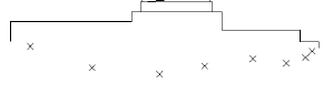
Figure 8.13 Fitting a spline to data points.
In the next step, you use the pre-positioned data points shown in the drawing by X points. A node running Osnap has been set so you can easily snap to these data points.
2. Start the SPLINE command by either entering SPL and pressing Enter or by choosing the Spline tool from the Draw toolbar. The Object/
3. Use the default option by setting an Endpoint Osnap and snapping to the endpoint at 1. The Enter point: prompt appears.
4. Continue to specify points, snapping to each successive X node at each Enter point: prompt. Finally, invoke another Endpoint Osnap and snap to the point at 2.
5. Press Enter to end the Enter point: prompt. The Enter start tangent: prompt appears.
6. A rubber band line stretches from the first spline point. Invoke the ORTHO mode (press F8) and pick a point near 3. At the Enter end tangent: prompt, pick a point near 4. AutoCAD completes the spline.
7. Turn ORTHO mode off by pressing F8 again. Your drawing should now resemble figure 8.14.

The completed spline curve.
8. You will use this drawing in the next exercise, but for now save your work by pressing Ctrl+S.
In the preceding exercise, you used pre-positioned points to help construct the spline. Depending on the type of work you want to do, you usually base splines on some form of preliminary data points rather than just draw the curve in free-form style, although both methods are available with AutoCAD. At best, splines are "tricky" objects to construct, and once drawn, you frequently need to alter or refine them.
Controlling Splines with SPLINEDIT
The SPLINEDIT command enables you to edit a spline's control points and, if present, fit-data points. When you draw a spline, you pick fit-data points. AutoCAD uses these points to calculate the location of the spline's control points. You can add additional control or fit-data points or move points already present. You can change the weight, or influence of control points, as well as the tolerance of the spline. You also can close or open a spline and adjust the tangent information of the start and endpoints.
Control points usually are not located on the spline curve (except at the start and endpoints), but they control the shape of the spline. AutoCAD uses the fit-data points to calculate the position of the control points. After AutoCAD determines the control points, it no longer needs the fit-data points. If you remove the fit-data from a spline, though, you cannot use any of the fit-data editing options of the SPLINEDIT command to further edit the shape of the spline.
When you select a spline for editing, AutoCAD displays its control points just as it does if you use grips editing, although grips editing is not available through the SPLINEDIT command. The SPLINEDIT command works on only one spline object at a time. The Noun/Verb selection method is not available with SPLINEDIT.
The SPLINEDIT command has the following options:
Fit Data. Enables you to edit the fit-data points for spline objects that have them, in which case, AutoCAD displays another prompt of Fit Data options described following this list.
Close. Closes an open spline. Adds a curve that is tangent between the start and end vertices for splines that do not have the same start and endpoints. If the spline does have the same start and endpoints, the Close option makes the tangent information for each point continuous. If the spline is already closed, the Close option is replaced by the
Open option.
Open. Opens a closed spline. If the spline did not have the same start and endpoints prior to being closed, this option removes the tangent curve and removes tangent information from the start and endpoints. If the spline shares the same start and endpoint before you close it, the Open option removes the tangent information from the points.
Move Vertex. Enables you to move the control vertices of a spline. You specify a vertex to edit by moving the current vertex to the next or previous vertex.
Refine. Displays suboptions that enable you to add control points and adjust the weight of control points. You can add individual control points in areas where you want finer control of the curve. Performing any refine operation on a spline removes fit-data from the spline. You can reverse the effect of the Refine option and restore the fit-data with the
Undo option before ending the SPLINEDIT command. The following list describes the Refine options.
Add control point. Enables you to add a sing le control point to a spline. AutoCAD locates the new control point as close as possible to the point you pick on the spline. Adding a control point does not change the shape of the spline.
Elevate Order. Elevates the order of the spline's polynomial, which adds control points evenly over the spline. This option does not change the shape of the spline. The order of the polynomial cannot be reduced once increased.
Weight. Controls the amount of tension that pulls a spline toward a control point.
eXit. Returns to the main SPLINEDIT prompt.
rEverse. Changes the direction of the spline.
Undo. Undoes the most recently performed SPLINEDIT option.
eXit. Ends the SPLINEDIT command.
The following are the suboptions of the Fit Data option for editing spline object fit-data. When you choose the Fit
Data option, the grips-like boxes change to highlight the fit-data points.
Add. Adds additional fit-data points to the curve. Adding fit-data points changes the shape of the spline curve. Added fit-data points obey the current tolerance of the spline.
Close. Performs the same function as the control point Close option using fit-data points.
Open. Performs the same function as the control point Open option using fit-data points. The Open option replaces the Close option if the spline is already closed.
Delete. Removes fit-data points and redraws the spline to fit the fit-data points that remain.
Move. Enables you to move fit-data point vertices of a spline. You specify a vertex to edit by moving the current vertex to the next or previous vertex. You cannot edit fit data information with AutoCAD's grips editing feature.
Purge. Removes all fit data from the spline.
Tangents. Enables you to change the tangent information of the start and endpoints of a spline.
toLerance. Changes the tolerance of the spline's fit-data points and redraws the spline. A spline loses its fit data if you change the tolerance and move a control point or open or close the spline.
eXit. Returns to the control point editing prompt.
In the following exercise, you edit the spline you drew in the preceding exercise using some of the options of the SPLINEDIT command. First, you reduce the number of fit-data points, and then you add additional control points to the spline by changing its order.
EDITING A SPLINE
1. Continue from the previous exercise. Remove the running node osnap.
2. Start the SPLINEDIT command by either clicking on the Splinedit tool on the Modify II toolbar, or from the Modify menu, choose Object, Spline. Select the spline you drew in the preceding exercise. The control points appear (see fig. 8.15) and the following prompt appears:
Fit Data/Close/Move Vertex/Refine/rEverse/Undo/eXit

Figure 8.15 The Fit Data option displays a spline's control points.
3. Choose the Fit Data option by typing either F or D and then pressing Enter. AutoCAD changes the control points to show the fit data points. Notice that the fit data points are not the same as the control points. The Fit Data prompt appears.
4. Choose the Delete option and then pick a couple of points. Note that the points disappear as you pick them. Press Enter after you remove the points. The prompt returns. Choose the Tangents option. The System default/
5. Press Enter to keep the current tangent. Then at the System default/
6. When the prompt returns, press Enter to return to the main control point prompt. The control points are displayed and the control point prompt appears.
7. Choose the Refine option, and then at the new prompt, choose the Elevate option.
8. At the Enter new order <4>: prompt, type 6 and press Enter. This elevates the order of the polynomial and adds control points. The prompt returns. Respond by pressing Enter to exit to the main prompt.
9. Press Enter again to exit the PLINEDIT command.
10. From the layer control box on the Object Properties toolbar, turn off the layer Frame. Your drawing should now resemble figure 8.16. You are finished with this drawing.

Figure 8.16 Completed spline-fit curve.
The options and sub-options of the SPLINEDIT command offer a great deal of control. In this exercise, you had the opportunity to investigate several ways you can modify and "tweak" a spline object. Splines are quite complex, but offer the advantage of also being quite accurate and flexible.
--------------------------------------------------------------------------------
TIP: As with polylines, the most efficient way to edit true splines often is to use AutoCAD's grips editing feature.
--------------------------------------------------------------------------------