Lynn Allen
Paper Space Dimensioning— (Part 4) Final
There are two very different schools of thought on dimensions as they relate to Paper Space layouts; one school believes the dimensions should be placed in Model Space, and the other believes the dimensions belong in Paper Space. Both choices have pros and cons. One year at Autodesk University we had two different Paper Space instructors: Shane Bartley of Disney, who was adamant that the dimensions belonged in Paper Space, and Dave Espinosa-Aguilar of Toxic Frog Multimedia, who absolutely believed they belonged in Model Space.
So who was right? I'm not about to tell you that one is better than the other, but I will share with you the pros and cons with you.
10,000 Feet Above
Let's look at the basics from the 10,000 foot level. If you're using AutoCAD 2000i or earlier versions and you place your dimensions in Paper Space, it's easy to ensure you're getting the proper text height, arrow size, and so on. You simply set the dimension variables to reflect the actual output value. However, when you dimension the Model Space objects from Paper Space, you immediately see that you don't get the proper dimension text value. In this case you have two options: override the dimension text value and key in the proper value (lots of work and very bad CAD manners), or you can change the Dimlfac (linear scale factor) to reflect the scale factor of the viewport. Hence we're back to the lovely world of figuring out the proper scale-factor settings. If your scale factor is 1:2, you'll set the Dimlfac to 2; If your scale factor is 1/4-inches=1-foot, you're really looking at a scale factor of 1=48, which means you'll set the Dimlfac to 48, and so on (see Setting Scale Factors in Paper Space (Part 3), for more information on scaling). All I know is that all this scaling gives me a serious headache, which makes me really love AutoCAD 2002. (Note: You can also set the Dimlfac value in the Dimension Style dialog box by setting the Measurement Scale factor in the Primary Units tab, as shown in Figure 1.)
 |
| Figure 1. You can set the Dimlfac value in the Primary Units tab of the Modify Dimension Style: Standard dialog box. |
If you place your dimensions in Paper Space, you'll also find that, should you move the model (accidentally or otherwise), your dimensions couldn't care less. They stay right where you put them. I refer to these types of dimensions as stupid dimensions--they have no idea that they're actually referencing an object on the screen. You can change the size of the object; the dimension ignores you. Those Paper Space dimensions will stay looking exactly the same regardless of what you do to the model.
Dimensions in Model Space
So that's one school of thought. Let's take a look at the second and more popular school: placing your dimensions in Model Space. To place your dimensions in Model Space, you'll need to set one key dimension variable to ensure you get the proper results. First and foremost, the Dimscale factor absolutely must be set to 0. This can also be easily set in the Dimension Style dialog box (DDIM or dimstyle) by checking the value "Scale dimensions to layout (paperspace)" under the Fit tab, as shown in Figure 2. Setting the dimscale to 0 will tell AutoCAD to take a look at the scale factor of the viewport and scale the dimensions accordingly. This will ensure that your dimension text, arrowheads, and so forth display at the proper value. Do not, and I repeat, do not attempt to manually set the dimension text, arrowheads, and such to the reciprocal of the scale factor; let AutoCAD do the work for you.
So what happens if you change the scale factor of the viewport? You'll see that though these dimensions are smarter (in that they follow the model), they don't automatically rescale to the proper physical values. Consequently, your arrowheads and text might appear too large or too small. However, a simple update (Dimension pulldown menu => Update) will correct this. Each time you change the scale factor you'll need to update the dimension. (Note: you can also use the -DIMSTYLE command [don't forget the dash] and the Apply option to yield the same results as well as the DIM command followed by UPD to utilize the old UPDATE command.)
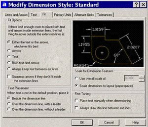 |
| Figure 2. The Fit tab in the standard Modify Dimension Style dialog box gives you the option to scale dimensions to layout (paperspace), as shown on the middle right side of this figure. |
One of the appealing features within Paper Space is its ability to individually control the display of layers within viewports. If you choose to place your dimensions in Model Space, you'll also want to make sure you create a separate dimension layer for each viewport. When creating multiple viewports, you will undoubtedly want to be able to control the visibility of the dimensions per viewport. For example, you can decide whether or not the DIM1 layer appears in any or all viewports. This will be discussed in more detail later in the column.
AutoCAD 2002
This takes us to AutoCAD 2002. One of the coolest new features in AutoCAD 2002 is Trans-spatial dimensioning. Yes, of course, this is another new AutoCAD buzzword (as though we don't already have enough). This new feature permits you to enjoy the simplicity of dimensioning in Paper Space while maintaining the intelligence of dimensioning in Model Space. Trans-spatial dimensions are smart; as you change the model, the dimensions update. Let's take a look.
First of all you'll want to make sure you turn on the new Associative dimensioning, as shown in Figure 3. Simply go to the User Preferences tab in the Options dialog box (or set DIMASSOC to 2) and select the "Make new dimensions associative" option. Now dimension your model from Paper Space by reaching into the viewport to select those parts that need to be dimensioned. It's embarrassingly easy and doesn't require any fancy scaling mumbo jumbo.
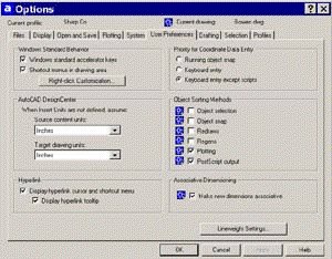 |
| Figure 3. You can turn on Associative Dimensioning in the User Preference tab of the Options dialog box. |
Note: The wonderful Quick Dimensions (QDIM) which came out in AutoCAD 2000 are not associative and consequently cannot create the smart trans-spatial dimensions. It just about broke my heart when I found this out since I'm such a huge QDIM fan. Layers in Layouts!
Since layers are so important when dimensioning in Paper Space, it's probably a good time to mention a couple of key ingredients to Paper Space success. It's not uncommon to want some objects to show up in one viewport and not in the others. You will control this by placing those objects on specific layers and then controlling their visibility in the LAYER dialog. While in a Layout you'll notice that there are two additional columns in the Layer dialog box: Current VP Freeze and New VP Freeze. You may actually have to widen the dialog box to see these columns since they land to the far right of the dialog. Current VP Freeze will freeze the selected layer in the current viewport, and New VP Freeze will freeze the selected layer in any future created viewports. You can easily freeze a specific layer in many viewports by highlighting multiple layers with the shift or control keys and selecting the icon in the Current VP Freeze column of one of the layers.
You can also freeze and thaw layers per viewport in the Layer drop-down list on the Object Properties toolbar (as long as you aren't in AutoCAD 2000). For some reason the Toolbar gods decided to remove this option in AutoCAD 2000 and replace it with the new no-plot feature. Realizing the error of their ways, this valuable option was restored in AutoCAD 2000i. You might find that you need to use various crosshatch scale factors to get the desired results in various viewports. It's not uncommon for users to have several different hatch layers to achieve the proper results.
You can also control your layers in the VPLAYER command. You may find the many different options that exist in the VPLAYER command to be more appealing when doing extensive layer control in viewports. Since you can use wildcards in VPLAYER, it's sometimes more efficient to use than manually selecting the viewports in the standard LAYER command. Besides, the VPLAYER command contains one of the most intimidating default options in AutoCAD: VPVISDFLT (Viewport Visibility Default). It only sounds scary, and works much like the New VP Freeze option does in the Layer dialog.
You'll also probably want to set your viewport layer to no-plot so you don't see the viewport boundaries on your final plot. Another important variable that needs to be discussed is PSLTSCALE. To ensure your linetypes display correctly in your viewports you'll want to set PSLTSCALE to 1 (or on). Then AutoCAD will take a look at your current viewport scale factor and scale your linetypes according to the LTSCALE and CELTSCALE settings.
One Final Tip
Have you ever tried to create aligned viewports using the MVIEW command? Good luck! The easiest method for lining up your viewports is by copying the viewports to the desired location and stretching the viewport (preferably by using your grips) to get the desired size.
So let's recap the proper process for living happily ever after in Paper Space.
- 1. Create Your Model.
- 2. Select the Layout tab and set up the proper paper size (along with other assorted print settings) in the Page Setup dialog.
- 3. Insert your boundary and title block.
- 4. Create layers for your viewports and dimensions. Make the viewport layer current.
- 5. Use the MVIEW command to create your viewports.
- 6. Set the proper viewport scale factor in each viewport (see last month's column for details) and pan around if necessary to get the proper view of your model.
- 7. Set your appropriate dimension layer current and create your dimensions in the space of your choice (AutoCAD 2002 users will use Paper Space; pre-AutoCAD 2002 users will probably use Model Space). Be sure to set the various dimension variables appropriately as mentioned earlier in this column.
- 8. Annotate your drawing (in Paper Space).
- 9. Set the viewport layer to frozen or no-plot.
- 10. Plot at a scale of 1:1 (and I recommend using the Layout option for plotting).
- 11. Pat yourself on the back for becoming a Paper Space guru!
It looks like we made it through Paper Space, and I hope I was able to help you . There's so much to the world of Paper Space.