
I cheated. The Dean's DUKW has instructions for a fully sprung suspension and up to 6-wheel drive. I went with 4 wheel drive, unsprung front axle, and a simple pivoting-bogey rear suspension.
Drive shafts
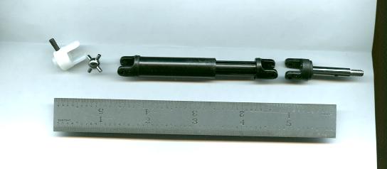
Driveshafts and universals come from Traxxas r/c trucks. The white yoke
(above) has a nice threaded cross pin for locking to the shaft... grub-screws
just don't work here! I reamed them out to fit 3/16" stainless steel
shafting. The stub shaft at right was used in the steering knuckle.
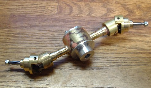
Rear Axle

Rear axle unit set in place
Rear suspension is a simple unsprung pivoting bogey, better than nothing. Elastic locknuts keep their place while allowing the joints to be loose.
Here's an experimental pivoting bogey on a CCKW 6x6 truck, which of course has
the same underpinnings as a DUKW.
The axles are made of various sizes of brass tubing, with lathe-turned aluminum caps.
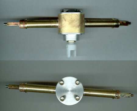

Oilite bearings inside, and 1:1 gearing with brass miter gears (some trial
plastic gears shown here).
Front Axle & Steering

Here's the front axle, almost done. It spins and steers at the same time! No
suspension beyond the springiness of the tires.
Front axle coming together, with knuckles in place. Steering arms were later
silver-soldered onto the knuckles.

Close up of the knuckles, with Traxxas cardan (u-joints) inside. The stub shaft
is stock Traxxas, and is meant to mount the wheels differently from what I'm
doing. The parts are all turned on my mini-lathe; I also have a set-up that
allows me to perform simple milling on the lathe, which I used to cut open the
sides.

The front wheels, with custom outer wheel halves. The stock Robart wheels could
be made to adapt to the Traxxas stub shafts, but this was cleaner. But more
importantly, the hollowed-out section visible on the right hand wheel above
allows me to offset the wheel inwards towards the knuckle, so there's much less
distance between the tire contact patch and the kingpin axis... makes for lower
steering effort, and minimizes the volume of space swept by the wheel as it
steers.
Wheel attachment is by simple set screw onto a flat on the stub axle; a
Nylock nut is used just to keep the wheel from possibly falling off. There are
better ways to drive a wheel, but I didn't have the precision tools to make them
and ensure that everything lined up just so.

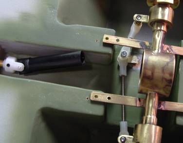
A stock servo, situated under the passenger's floor boards. A custom arm is
bolted to the bottom of the stock servo "horn"... I refused to pay $10
for a pack of heavy duty servo horns!
The steering shaft is vertical, like a rudder post. The picture shows Du-Bro
4-40 rod ends... a waste of money, they're very stiff. I replaced them with Nelson
Hobby rod ends, much smoother.
A view underneath; you can just see the steering "Pittman arm" under
the despicable Du-Bro rod ends.
A worthwhile detail: All my linkage arms have a 4-40 tapped button
silver-soldered on, so I can run the attaching screw straight in, with no nuts
to deal with.
Note: Real DUKWs steer the rudder and wheels together; I did the same by
Y'ing the steering servos together. This seems to work well, with the front
tires acting as additional rudders... this DUKW is quite maneuverable!
Prop & Rudder

Here's a view of the prop in it's tunnel; the rudder is brass, silver-soldered
to the
stainless steel post.

And the rudder servo mounted in the aft-port corner.
The odd pushrod is needed to make the front and rear steering work together.
Juice

A pair of 3000 mAh 7.2v packs provides plenty of operating time and a bit of
ballast. They're Velcro'd to the top of the front fender wells.
Not seeing this page in frames?
Get my frames back!