
Tools and materials required:
Warning: The water pump is below the water line and when the lines to the pump are removed water will pour into the boat. I had my boat out of the water when I changed the impeller.
Procedure: Loosen the idler pulley and remove the drive belt. Make note of the way the belt wraps around the various pulleys. Remove the two 9/16th bolts that hold the pump and bracket to the engine. You will now have enough room by pulling the pump out of the front of the engine to get to the two hose clamps on the water hoses. Mark the two hoses so you get them installed correctly. Loosen the two hose clamps and pull the hoses off the pump.
I took the pump to my garage so I had access to a vise and wire brush. The wire brush was helpful in cleaning the bolt threads to make it easier to remove them. Mark or make note of proper position of the bracket on the pump. Remove the three nuts holding the bracket to the pump. Remove the 5 bolts holding the plastic pump to the metal end. Lightly coat the inside of the pump housing and the new impeller with the Vaseline. The Vaseline protects the new impeller as it will run dry for a few seconds when first starting the engine. Install the impeller in the new pump housing. Install the smaller gasket around the pump shaft, and install the new wear plate. Install the new gasket on the plastic pump, and then the plastic pump to the front half of the pump. Coat the new bolt threads with Loctite. Install the two shorter bolts and just snug them down. Install the remaining three long bolts after coating with Loctite. Tighten all boats in a cris-cross pattern. I set my torque wrench to 50 inch pounds, tightened all bots then increased the torque setting on the wrench till I reached 110 in. lbs. or just over 9 ft. lbs. Install the mounting bracket to the pump. Hold the heads of the bolts when tightening the nuts on the mounting bracket.
Reverse the order of installing the pump back onto the motor. Install the drive belt and set the tension with the idler pulley. Make note in your maintenance log of the date and number of hours on the motor when you changed the impeller. Total time involved was about 2 hours. This is a maintenance that can be handled by most weekend wrench-turners.
Installing the Bennett ATR
Tools and material required: Installition
Since I keep my boat in a boatel I have to remember to retract the trim tabs or they will be torn off the boat when the forklift truck picks her up. Since I almost forgot to retract them one time I thought it would be better to install this device. The unit costs about $80 and takes about 45 minutes to install. The directions say to splice the three wires into the trim tab wiring harness. I found it much easier to attach them to the back of the tab switches. So, three wires connect to the back of the trim tab switch, one wire is ground, and there are two 12-volt wires. One is connected to a fused 20-amp 12-volt source, and the second 12-volt wire is connected to a voltage source that is turned off such as the start switch. Since I sometimes drift fish and would be starting and stopping the engine I connected the switched wire to the switch for my factory in-dash depth meter. When I turn off the depth meter as I am securing the boat, the ATR retracts the tabs making it safe to have the forklift pick up the boat. The ATR came with directions for connecting it to Bennett tabs and also Boat Leveler tabs like my Bayliner had.
Replacing the risers and elbows on a 5.7 liter Mercruiser
My engine had about 240 hours on it when I decided to tackle this maintenance. I bought the boat used and it had been used in salt water, in the Chesapeake Bay, for 5 years with only the last year having been flushed with fresh water after use. I was not having problems with over-heating, and could not see any water leaks. The starboard elbow would run warmer to the touch then the port one, but I could still holder my hand on it for 5 seconds or so. The port elbow I could hold my hand on it as long as I wanted to. I just wanted to protect my investment so I wanted to inspect the risers and elbows.
Tools required: 9/16" sockets, 9/16" open and box wrenches, lead hammer, torque wrench capable of setting 33 ft. lbs., screwdrivers, vice-grip pliers, torch, Liquid Wrench penetrating oil, razor blade scraper, putty knife, vacuum cleaner, Band-Aids for the cuts you'll receive while working in the engine compartment, Ibuprofen to relieve your sore muscles when you're finished.
Warning: My boat was out of the water when I did this as some parts of the exhaust system are below the water line and would have allowed seawater to pour into the boat with the exhaust system open.
Procedure: Turn off the battery switch. Remove the shift cable mechanism and ignition module from the elbows. Remove the two drain plugs and drain the water from the manifolds and risers. Loosen all hose clamps on the exhaust system. On my engine the elbows sat on top of 3-inch risers. The elbows connect to a 90° exhaust pipe, and the other end of this exhaust pipe connects to the lower "Y" exhaust pipe with another hose. Do not make the mistake I made. I could not figure out how to slide the 4-inch hose off of the elbow. This hose I found out has a rib inside it so it will not slide down onto the 90°exhaust pipe. I thought I'd just cut the hose off, as it is probably only $20. Well it is not $20 but $52. The lower hose on the 90° exhaust pipe will slide down so that you can then remove the 90° pipe that connects to the elbow. Remove the four 9/16" nuts that hold the elbow and riser to the manifold. If you are fortunate you can use the lead hammer to gently hit the bottom of the elbow while pulling upwards on the elbow at the same time to remove it from the riser. Once the elbow is removed, I tried to remove the 4 mounting studs as I cold not get the riser to slide up off of the mounting studs. Once the elbow is removed I used the putty knife to separate the seam between the riser and the manifold. On both of my risers one of the 4 mounting studs was rusted in the riser. I used vice grip pliers to remove the 9 ˝" long studs. On the starboard riser it took me 20 minutes to remove the stud and riser. It took me about 30 minutes of pounding on the port elbow to finally get it off the studs and riser. I used the putty knife to drive into the joint between the riser and elbow. On the port riser the stud was firmly rusted into the riser. I could turn the stud about 1/3 of a turn and the riser would turn along with the stud until the riser hit a fitting on the manifold. I soaked this stud with penetrating oil. I spent probably 2 hours trying to remove this one mounting stud and riser. I made sure there was no gas fumes in the bilges, then I finally applied heat from a propane torch 3-4 times to the corner of the riser where the stud was frozen in place. I would apply heat, then penetrating oil, then try to turn the stud using the vice grips with them set as tight as I could fasten them on the stud. In the mean time after I had cut my leg for the third time I finally re-positioned a hose clamp on the port manifold to protect my leg. At this point I had been bent over in the engine compartment for 4-6 hours. In between I went to two local Mercruiser dealers to buy new elbows, risers, gaskets, and mounting studs. My marina owner suggested I use Mercruiser parts rather then after-market. I figured he didn't sell the parts so he had nothing to gain by saying this. He said the Mercruiser parts would last longer. By this time I had already made up my mind this was going to be the last time I changed the elbows. The next time it would be required I would pay someone to do it.
With elbows and risers removed, I used the razor blade scraper to remove the old gasket from the manifold. I used the vacuum cleaner while doing this to catch any of the old gaskets before they could drop down into the manifolds. I then used a screwdriver to scrap any of the loose rust I could see from the water passages in the manifolds and again used the vacuum to catch the loose rust. I had now been working on this project for 7 hours counting the two hours I ran around getting the new parts. It would take me another two hours to put everything back together and gather up my tools.
Both Mercruiser dealers told me I did not need to apply any sealer to the new style gaskets. I took them at their word. At this point I was getting too tired to do much thinking on my own. I installed the mounting studs by running two nuts together on the upper ends of the studs and treading them into the manifolds after applying some anti-seize to the threads. I installed the new gaskets, risers, and elbows. The nuts were torqued to 33 ft. lbs by working up to this level in three stages and in a crisscross pattern. Install the 4 hoses, tighten all 8 hose clamps on each side of the manifolds. I sprayed a little soap solution on the hoses to make them slide over the exhaust pipes a little easier. Re-install the shift mechanism, and ignition module. Don't forget to install the manifold drain plugs.
By now I had been at it for 9 hours, with very muscle in my legs and back hurting, and numerous cuts on my legs arms, and hands. I watched as other people were loading their boats and heading out for the weekend. I just wanted to survive a hot shower, take some Ibuprofen, and climb into bed. I would do this job again if I were in my 30-40's but never again since I am in my late 50's. Looking at my elbows and risers I would guess that I could have gotten another 1-2 years out of them but now I feel I'm good for another 4-6 years since I now flush with fresh water after each use. The risers, gaskets, new studs, elbows, and one new 4-inch hose cost me $598. If I were younger and know what I know now, I could probably do this job in 3-4 hours if there were no problems removing any of the studs. Hopefully this will have been of some help to you should you decide to tackle this task. Ah, the joys of owning and trying to maintain your own boat.
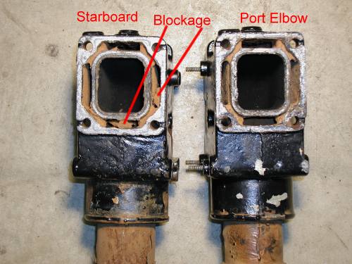
In these pictures it looks like most of the water passages are blocked but it is only the angle of the camera and the flash when I took the picture. You are actually looking at the rust on the walls of the water passages. The red lines are pointing to the only two blockages and one is very minor. There was no blockage in the port riser. You can also see one of the mounting studs still stuck in one of the risers.
Replacing the water pump impeller on a Bravo III
Installing a Bennett automatic trim tab retractor
Replacing the elbows and risers on a 5.7 L Mercruiser
Installing the Navman F2100 Fuel Flow Meter
Impeller Replacement
Socket wrenches, 9/16th box wrench, torque wrench capable of measuring 10 foot pounds, Loctite for threads, Vaseline Petrolem Jelly, and of course a water pump replacement kit that includes the impeller, plastic housing, stainless steel back plate, two gaskets, and new bolts.
Besides the Bennett ATR, several terminal connectors, pliers to crimp the connectors, a voltmeter or DVM
|
|
|
(2) 3/8-inch brass hose barbs with Ľ inch pipe threads.
(1) 90° brass elbow with 1/4 –inch pipe threads
(1) Tube of Permatex 2A gasket sealer
(4) stainless steel hose clamps
several cable ties
2-inch hole saw
Vairable speed drill
several wrenches to fit fuel line fittings
(2) push-on terminal lugs
Installation:
Not that it makes a lot of difference but this installation was done on a Bayliner 2655 with a 5.7 liter and a Bravo III out drive. I used the bracket that holds the out dive oil reservoir to mount the transducer.
It took the help of my daughter and an electrical fish tape to run the cable from the transducer to the readout unit. This took us almost an hour as the fish tape kept getting stuck in the wiring tube. I bought a 2 inch hole saw to drill the dash for the readout unit. I took my time, used a battery powered drill, and had no problem drilling the hole in the dash. Make sure you have room behind your dash before you drill the hole. In the place I had intended to mount the readout, I found that the other gauges took up too much room behind the dash with their mounts. I used the mounting bracket from the Navman to check for room behind the dash before I drilled the hole or I would have had a 2 inch hole in the dash and the readout mounting bracket would not have fit. I got power for the readout from the ignition switch.
I read any article I could find on how to mount the transducer. I have a spin-on fuel filter that looks like an oil filter. I didn’t want to install a second fuel filter. I removed the 3/8-inch stainless steel line that connects output side of the fuel filter to the fuel pump. I removed the 90° fitting from the fuel filter and installed a Ľ-inch brass pipe 90° elbow on this fitting and into the other end of the 90° elbow I installed a 3/8-inch hose barb fitting. I then connected the other end of the stainless steel tubing back onto the fuel pump. I installed a 3/8-inch brass hose barb fitting into the inlet of the fuel filter where the stainless steel tubing going to the fule pump had been removed. I used 3/8-inch CG approved gasoline hose to connect the hose barb fittings to the transducer. The hose was secured with stainless steel hose clamps. All pipe threads were sealed with the Permatex 2A to prevent leaks.(Picture below left) I leak checked all fittings by running the engine with ear muffs on the out drive to provide cooling and had to tighten one fitting as there was a slight leak. I secured the transducer to the bracket that holds my out drive oil reservoir using a large cable tie insuring the transducer was in the vertical position. (Picture below right)
  |
One thing to remember is that the readout is set for liters per hour as it comes from the factory and must be changed to gallons per hour.
Other Boat Modifications w/Pictures
Email me at:carrollwb[at]verizon.net
This page was last modified on 5/29/05
This page has received  hits since June 2004.
This page hosted by ![]() Get your own Free Home Page
Get your own Free Home Page