
Hayseed, A Miniature Farm Engine
new 12/14/2001, additions 1/26/02 and 2/5/03
I have added a video of Hayseed's hit & miss governor, here.
A few months ago, I took a notion to build my first internal combustion engine. I wanted an old style engine, but since it was my first, something simple seemed in order. A trip through the back issues of Strictly IC magazine yielded Hamilton Upshur's Farm Engine (Mk 2). Hamilton had designed the engine originally back in the early 90's, but since then had made some improvements. Bob Washburn published the revised engine plans in SIC in issues 77 through 79. By November, I had made substantial progress on the engine, and took the still unfinished product to SAMS (The South's own Model Engineering show in Dutton, Alabama). Bob Shores was there with his engines, and I got valuable advice from him and from Robert Russell, a model maker from Childersburg, Alabama.
At the time, I had not worked out the ignition system in my mind, so Robert's advice was invaluable. He uses buzz coils on his engines, and they all run beautifully. Bob had admonished me to "keep it simple", so I settled on a buzz coil and mechanical points. I had a buzz coil that had been on the shelf in my shop for at least 25 years, condition unknown, so I checked out the web for info on buzz coils. That led me to Paul Pavlinovich's site, information on the innards of buzz coils and plans for a buzz coil tester at steamengine.com.au. It is an Australian site and contrary to its title, has information on lots of things including steam engines.
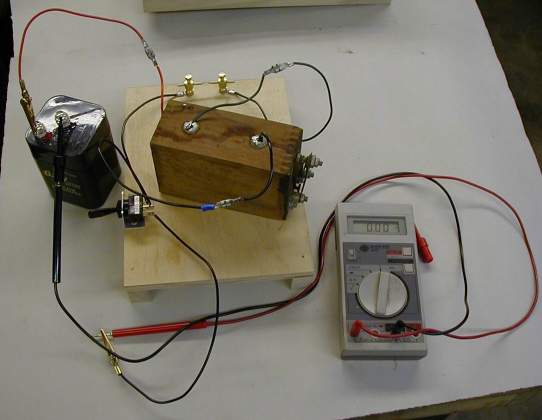
| So, my first step was to check out the buzz coil. Here is a photo of the test layout. My digital meter has a 10 amp scale which makes it ideal for this test. Hardly any adjustment was required, and the result was an intense blue spark across the spark gap. | |
|
The test bench was simple to make, but quite necessary. It is hazardous to the health of a high tension transformer to be operated without a proper load. If the insulation in the transformer is weak, it will arc over and damage the windings, probably fatally! The only parts I had to make were the spark gap binding posts and the switch bracket. I used an automotive type toggle switch rated at 12 volts, 20 amps, well above the expected amperage of the test setup. The battery is a Radio Shack 6 volt sealed lead acid battery rated at 5 ampere hours. At the time of this writing I have run the engine for about an hour, and the battery is still substantially at full charge.
So now for some views of the engine. As usual, click on the small image for an enlarged view.
|
|
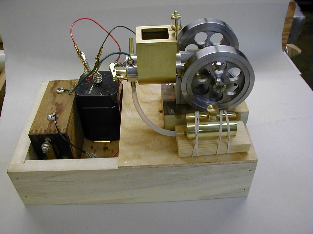
Here is the Hayseed on the test stand. The gas tank is securely rubber banded to a small block to bring it to the correct height. In the final incarnation, it will have a proper bracket to secure it to the running stand. |
| One of the departures I made from Hamilton's drawings was the attachment of the flywheel to the crank shaft. I originally drilled the flywheel hubs for setscrews, but wanting to have more latitude for adjustment, I made split collets. You can see the split in the left. It was made with a jeweler's saw. The two holes are threaded for jack screws so that the collet can be released when necessary. When the 3 clamp screws are tightened, I can not rotate the flywheels on the shaft. |  |
 |
Here is a closer look at the head and the water jacket. I followed Hamilton's drawings pretty closely on the head, but I wanted a slightly larger water jacket. Because the pushrod for the exhaust valve runs close to the cylinder, I had to run a small brass tube through the water jacket for the push rod. (Of course it was planned that way, you don't think I make mistakes, do you...) |
| The points were adapted from a set of automobile points. I had good success soldering the lower point on the 2-56 adjusting screw, but the upper point just refused the solder after repeated attempts. Then I tried silver brazing the point to the spring. Success at last! |  |
This was a fun engine to make, and Hamilton's construction notes are set out
with a beginning machinist in mind. I highly recommend it to you aspiring engine
builders. Strictly IC ended publication with the last issue of 2001, so no more
issues will be forthcoming. Bob Washburn does still offer back issues, so if you
are interested in building this engine, drop by StrictlyIC.com and place an order.
January, 2002:
The engine is now complete. I have made a finger jointed box for it, and have the buzz coil and battery inside. Here some photos:
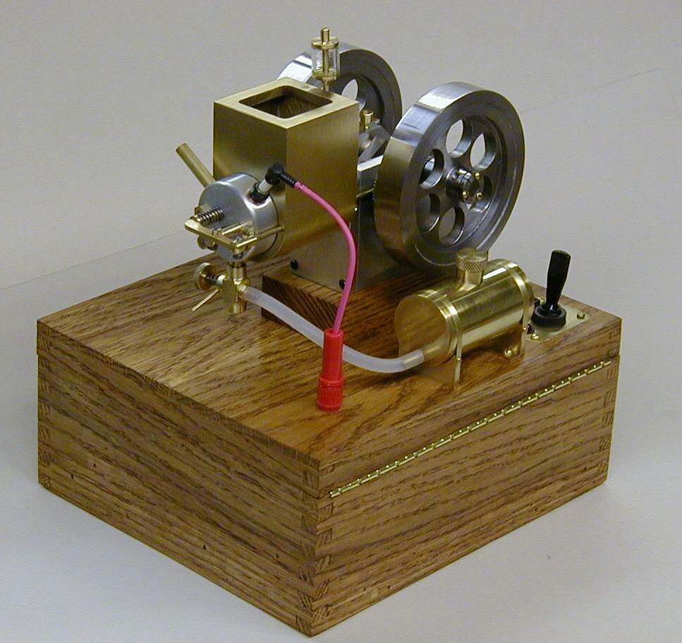
| Here it is! A few changes have been made: A new carburetor has been made, another of Hamilton's designs, with throttle. The gas tank has lost its rubber bands and found a couple of brass brackets. |
|
|
|
Rear quarter view here. I was pleased with the power switch inset into the top of the box. It is an automotive type switch, rated at 15 amps at 12 volts. Probably a bit of overkill, but it won't burn out any time soon. The spark plug wire is brought through the box via a banana jack and plug. The spark plug wire is from Bob Shores. Gives the engine a nice finished look, I think. |
| Here is a closer look at the gas tank and power switch.
Hidden behind the toggle switch is the battery charging jack. I have
made a battery charger with regulated output to keep the sealed
lead-acid battery properly charged. I will describe it on another page
and will link from here when it is done.
The straps for the gas tank were cut from .006 shim brass on an old paper cutter. It worked great and didn't distort the brass like cutting it with shears would have. A bit of Mother's chrome polish shined them nicely. |
|
|
|
Here are the "innards" as they used to say in East Texas (where I was born and raised!) I screwed 2 brass strips to the left inside of the box, The springs on the battery contact them, and soldering tabs provide wiring connection. The block of oak at the base of the battery holds tension on the contact springs. On the inside top near the right is the connection to the banana plug for the spark wire. Most connections are made with spade connectors so that the buzz coil can be easily removed. The charging jack has a normally closed contact that is opened when the charger is connected which prevents any load on the system while charging. |
| Ready for action! The LED is glowing brightly, showing that there is power to the buzz coil. A bit of gas in the tank, a few flips of the flywheels and away we go! This has been a fun project, and I hope you have enjoyed sharing it with me. |  |
January, 2003
My first show with Hayseed performing was the Cabin Fever Expo in York, Pennsylvania. Being from the south, I didn't have a lot of tolerance for 4 degree weather, and driving through a snow storm in Tennessee was a traumatic experience. But the show was great and My friend Dewayne Lockler and I were able to find other members of the Florida Amateur Model Engineers (FAME) who we knew by correspondence only. We all stationed ourselves at the same table, and had a fine time comparing notes and admiring one another's models.
I also had the opportunity to meet
Hamilton (Dick) Upshur, the designer of Hayseed. He is a most gracious
gentleman, and free with advice and help. He was pleased to see the engine, and
remarked that he had designed a hit and miss governor for it. I had put the
throttling carburetor on Hayseed to slow it down a bit, but it never was very
happy unless it was running pretty fast. So, I purchased Dick's plan set for
four farm engines which contained the design information on the H&M
governor.
Hayseed. He is a most gracious
gentleman, and free with advice and help. He was pleased to see the engine, and
remarked that he had designed a hit and miss governor for it. I had put the
throttling carburetor on Hayseed to slow it down a bit, but it never was very
happy unless it was running pretty fast. So, I purchased Dick's plan set for
four farm engines which contained the design information on the H&M
governor.
Of course, since I had modified Dick's original design with the larger water tank, I had to make extensive changes to Hayseed to meet the new design. The first order of business was to scrap the large water jacket. then a flywheel modification was in order, and finally parts making and fitting the new governor. I am happy to report that all went well, and now Hayseed putts along in a fairly leisurely manner. I may change the flywheels to a larger diameter, and that should make it even a bit lazier - but that's another project!
Here is photographic evidence of the changes:
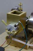
| The original |
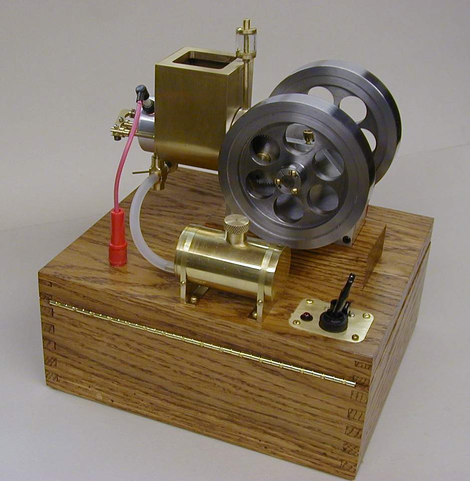
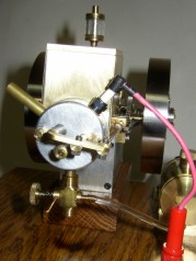
As modified |
 |
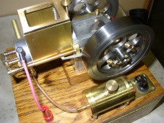 |
| The original, complete with large water jacket and silicone fuel line | A slimmer water jacket, exposed pushrod and a more heat resistant fuel line |
|
|
 |
|
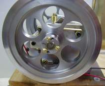
Right side flywheel, but the left one is identical. |
Left side with governor weights. I left pegs on the ends for springs, but found they weren't necessary. |
|
|
|
| The head and water jacket as originally configured with original carb. | New, slim jacket, the new carb. Brass pushrod guide just below the spark plug. |
|
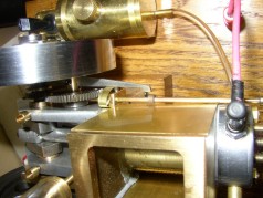
Some details of the governor. |
|
|
|
|
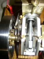
| Inside of left flywheel showing governor thimble and the rear end of the exhaust valve latch. See above for the outside of this flywheel. | The push rod has a lug that is trapped by the exhaust valve latch. A .006 brass spring holds the latch open until centrifugal force spreads the governor weights and pulls the thimble outward. When the engine slows, the latch is released, seating the exhaust valve and allowing the engine to "hit" |
The modification is a success, and Hayseed will make his next debut at the meeting of the North Georgia Metalworkers ("Metal Munchers") Tuesday, February 11, 2003