|
|
|
|
|
In
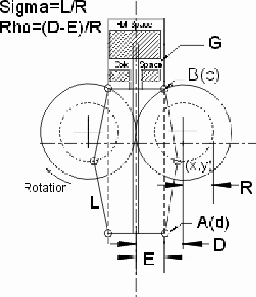
designing the Test Tube Rhombic, I used information from Dr. Senft's book
"Ringbom Stirling Engines". In his description, he defines four variables
of the Rhombic Drive and two functions of these variables. These are shown
in the table below, and are:
R, the crank radius
L, the length of the connecting
rods (assuming all are equal)
D, the pitch radius of the
gears and
E, half the pivot center
distance of the connecting links.
These are illustrated in
the drawing to the right on this page.
The two functions are sigma
= L/R and rho = (D-E)/R.
He then goes on to say of
the ratios sigma=2.6 and rho=.97 "This parameter combination yields an
exceptionally good cycle." without further explanation, but with a graph
such as the one on page 3 of this document. I began by choosing a convenient
gear pitch radius and crank radius. Plugging these into the equations gave
me the remaining lengths. |
|
|
|
|
|
|
|
|
|
|
|
|
|
To
verify that I would have approximately the same movement diagram as Dr.
Senft, I put these values into an Excel spreadsheet, which you see here.
I began by calculating the x and y coordinates of the crank
pin (x and y below), and the y coordinate of the link pivots (Y(p) and
Y(d), the position of the power piston and displacer piston link centerlines).
I needed one side only, since the Rhombic drive is symetrical. The above
drawing should help make this clear. |
|
|
|
|
|
|


