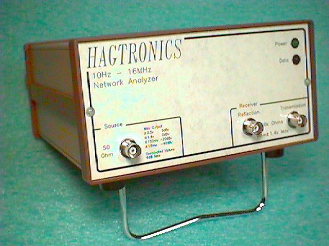
Personal Network Analyzer
By: Steve Hageman
The
construction article was published in the January and February, 1998
issues of QST.
NEW:
Courtesy of the ARRL/QST the entire article is now on line
here!
 Please note: As of December 2001 parts are getting
hard to get for this project and I can no longer support the project.
Take a look at my more modern 2-250 MHz network analyzer on my main
site.
Please note: As of December 2001 parts are getting
hard to get for this project and I can no longer support the project.
Take a look at my more modern 2-250 MHz network analyzer on my main
site.
OVERVIEW:
This project is an
RS232 controlled Scalar network analyzer for personal use. The design
uses a Harris 45102 DDS source (10 Hz-16 MHz), and two receivers made
from Philips NE604 IF strips. Using the IF strip RSSI output I was
able to achieve about 50-60 dB of dynamic range. My usual control
method was used, i.e. A PIC in the box to control the RS232 interface
and decode commands for the hardware. The control program is a full
fledged Visual Basic program that provides a network analyzer
interface to the user. Click HERE for an example screen shot of
the analyzer measuring a 455 KHz ceramic IF filter, or click
HERE to see a screen shot of the
analyzer measuring a 10.7 MHz IF filter, this shot shows the
on-screen cursors being used to measure the 3 dB bandwidth of the
filter. One really notable feature of this design is that using chips
developed for the wireless market, it took only 15 IC's to make this
thing.
Who say's you
can't build anything anymore as a hobbyist!
Some of the uses
are:
- Testing
filters
- Testing audio
amp circuits
- Testing /
tuning IF circuits
- Use of the
source as a precise (1 Hz resolution, 100 ppm accuracy),
adjustable output amplitude bench source
- Learning
The goal of all
this stuff is to make the job of designing low frequency circuits a
science, instead of guesswork. If you can measure what you build
quickly, you will get better results than if just build and see if it
smokes!!
SOFTWARE:
A complete software
package is available free from the ARRL
files site as
'hageman.zip'. The program runs on Win 3.1, 3.11, 95, 98 and was
tested on one NT4.0 PC. I can't support NT if it does not work
however, sorry. A good test is to get the program files from the ARRL
and run the setport utility. It won't set up the Analyzer, but it
should show if the program will run.
If you can program
your own PIC16C71 download the object code for the PIC
here (Right
click and save as...). Be sure to set the programmer to WDT OFF,
Power Up Timer ON, and XT oscillator (Don't code protect a EPROM
device!!!!! It won't program again). This code is in Intel HEX8
format and works with the Microchip PicStart and other programmers.
You must manually configure the fuses! Fuse info is not in the hex
file.
PCB's:
Fred at FAR
Circuits has
PCB's available for this project (a 4 board set: 2 receivers, 1
source/uP and a power supply board).
Analyzer - FAQ's
Please e-mail with
your questions and if you have found parts anywhere. That's how this
all works, you share with me, I'll post it so everyone knows -- and
I'll give you credit too!
Thanks for every
ones kind words so far! It really helps to inspire me to do more of
this.
1) The software
package (see above) contains a HEX file for programming your own PIC
(if you have a programmer). Otherwise you can obtain a pre-programmed
PIC from me for $15.00 USD (Check/Money
order only, no credit cards).
Overseas: Please
see what it costs to ship 2 ounces (60 grams) to your destination
from California USA, and add that amount also. If you tell me how you
want it shipped with your order and include enough to cover the
method, I'll do it that way. Thanks!
I usually ship the
same day I receive your order.
2) The schematic
printed shows U5 as being a 'HSP14502', the part number really is a
'HSP45102'.
3) The Receiver
schematic shows R3 as being a 5k, 10 turn pot and the parts list says
'1k'. 5k is the correct value.
4) Be sure to check
the FAR PCB's for shorted traces before building. These are pretty
easy to spot. The look like a blob on a trace or at a trace corner
that should not be there. If you find one, us an XACTO knife to
remove the short.
5) As of 1/98 the NE604AN IC
seems to be hard to find. I suggest that you look for an SA604AN
(Same part, industrial temp. range). Another possibility is to buy a
SMT device and 'air' wire it to the PCB using small wire wrap wire.
Or you can buy an SMT adapter from Mouser get a Philips SA604AD, SMT
part and put that on the FAR circuit board. The part numbers
are,
Mouser lists that they have a 16 pin
SOIC to DIP adaptor P/N 535-16-350000-10
Philips web site has links to many
distributors on line (follow the links to find parts). Allied
generally has SMT versions of the part.
Bob reports that
TechAmerica has SA604AN's (DIP
Parts)!!!!! Search for SA604. Thanks Bob :)
6) One thing I did to
keep 60 Hz noise out of the box was to roll the receiver bandwidth
off below 100 Hz. This lowers the dynamic range at 10 Hz. It can make
for some less than optimum wide band plots (i.e. 10 Hz to 100 KHz for
example). Usually at 100 Hz the source may switch attenuators to
re-optimize the SNR. This can create a 'bump' in the display that
does not look really pretty. There are two way's to handle this: 1)
Set the sources to a fixed value during a sweep. 2) Sweep 10 Hz to
100 Hz then 100 Hz to whatever and look at the plots individually. If
this is not acceptable, you may want to lower the receiver response
rolloff point to 10 Hz (just be careful of 60 Hz noise!). To lower
the receiver response all the way to 10 Hz, change the following
parts on BOTH receiver boards,
C12, 13
from 1 uF to 10 uF Tantalum, 25V
C1, 2, 3, 4 from 22
uF to 47 uF Tantalum, 25V
7) Allied electronics has AD847's and
most all of the other semiconductors.
8) Digi
Key has the
CA3338's (if Allied does not).
9) Mouser has a large selection of
box's for putting the PNA in (as does Allied) and SMT to DIP adapters
(Thanks to AB6KS for the lead!).
10) Harris
semiconductor has a web link that lists all their distributors:
www.semi.harris.com/contact/index.htm I last found parts at Allied,
Rochester and Gerber. It is possible to use an Aries SMT adaptor for
SMT versions of the 45102 also. See #5 above.
11) A few questions
have come up about the shielding that was talked about in the
article. If you use the FAR circuit boards, no shielding is required
on the PCB itself. It is a good idea to put each receiver in its own
mini-box though. Then tie the receivers boxes to the chassis. I would
recommend that a metal box be used for the chassis. The receiver
bandwidth is >25 MHz so they are susceptible to RF pickup. Use
good RF grounding for the receiver portions.
12) The Pinout for
the BS250 shown on page 40 of the QST article is correct. It turns
out that the silkscreen on the FAR circuit boards is backwards (due
to my error in the information I sent FAR). The lettering on the FAR
board is correct, it's just the outline that is backwards. The VN2222
has the correct pinout and part silkscreen on the FAR boards.
13) Make sure that
you buy a LM2931AT-5.0 part for the +5 volt regulator not just a
LM2931CT. The LM2931CT is an adjustable type, not fixed at 5 volts,
it also has 5 pins (thanks VE7CA for the heads up).
14) A sharp eyed
reader noticed that figures 9 and 13 (Feb issue) are quite
susceptible to loading errors caused by long lead lengths back to the
PNA. He is right of course, and the text leads one to believe that
the fabricated probes that I showed are being used for these
measurements. The probe construction as I presented them may have
20-50 pF of capacitance at the probe tip. I actually used small
fixtures that plugged in right at the input spigots of the PNA for
these measurements (with very short lead lengths). Please keep in
mind probe capacitance and possible associated loading errors when
using the PNA. When in doubt keep those leads short! The probes are
still very useful for low impedance work (as shown in the other
examples) and they keep noise out of the analyzer + they are easy to
use. If you wish to make precision impedance measurements the best
bet is to use a return loss bridge as I mentioned in the article (see
the ARRL handbook).
15) Jay reports that
C15 is shown on the schematic as 0.1 uF (Figure 2), but the FAR
silkscreen is shown to be 0.01 uF. Either value in the circuit will
be OK. - Thanks Jay for the info.
16) Jay also confirms
that everyone (I've run into this before) is having problems with C33
in figure 4. The ARRL says that 'Decimal' values of capacitance are
uF all others are pF. This means that 0.1 is 0.1 uF and 4.7 is 4.7
pF. Tricky -- eh? First time I looked at it I thought they meant 4.7
uF also, but not so the ARRL informed me. Thanks Jay I'm sure this
will clear things up for others also. BTW - C33 is 4.7pF!
17) Jay is busy, he
has also found that the silkscreen on C12 and C8 on the FAR receiver
boards do not match the schematic in QST. C12 in the QST schematic is
actually backwards from my schematic that I sent them. So the QST
schematic is incorrect and the FAR PCB is correct. C8 must be as per
the QST schematic for the linearity to be correct if the capacitor
leaks at all. Thanks, Jay.
18) Q: When I click
on the cursor menu all I get is a box with nothing in it (also no
cursors). A: This is normal, you need to move one of the cursors
before the box will fill with text or the cursor(s) will display. To
move the red cursor press the left or right arrow keys. To move the
green cursor press and hold the shift key while pressing the right or
left arrow keys. After either cursor is moved the box should display
the frequency and dB value for the red (R), green (G) cursors and the
delta (D) reading between the two cursors.
19) Q: When I go to a
sweep for the first time the Hz, kHz and MHz list box does not
display properly next to the start and stop frequency input boxes.
When I sweep a second time they (may) appear. I am running Win3.1.
What is going on? A: I cannot recreate this problem on any of my
computers. These types of screen writing problems are usually caused
by the display driver in use by windows. One thing I can suggest
right now is to switch to Windows generic VGA driver in 640x480 mode,
or I have a modified version of the program available that removes
the offending controls and allows input of start and stop frequencies
in kHz directly. If you have this problem and would like a copy,
e-mail me and I will e-mail you a copy (I only need to send a 60k exe
file).
20) Q: The control
program does not seem to run on really old hardware (i.e. before
486DX2 platforms) A: If you run into this, edit the delay parameter
in the analyzer.ini file (instructions are in the file). This adds a
slight delay in the RS232 readback functions so that the hardware and
software can catch up to each other. This can also happen if your
UART type is not a high speed 16650 type (most brand name 486DX and
above computers have this type of UART).
21) A free program
called PartMiner is available from partminer.com. This nifty program
will search a dozen US sites for parts that you may need. Try it,
it's how I keep up to date on what is available where.
Sorry they
went bust!
22) The only
'generic' problem that has shown up several times now is that some
people have tried to build the PNA by substituting Aluminim
Electrolytic capacitors instead of the Tantalum ones called out for
in the schematic. This is not a good idea, especially around the
NE/SA604. The Tantalums were called out because of their leakage
characteristics. If you use Aluminum Electrolytics instead the end
result is really poor linearity and attenuation accuracy.
|Comments?| |To
Steve's Workshop Home|
Modified -
7Jan01