|
Eric's VW Page |
|
|
1967 Beetle Restoration Page
Before: These are different views of the car before I started fixing anything. These were all taken around the first of May, 1999. Pic 1 left side. Pic 2 front view. Pic 3 rear view. If you look closely, you can see that my decklid is propped open a little. I made a block to prop it open to let in more air for the 1600 engine when it got hot outside. Pic 4 view of the dash. Pic 5 shows a good view of the somewhat stripped interior before I removed any switches or wires. The yellow stuff is old glue that had held in my orange shag carpet years ago. Pic 6 is looking down where the gas tank was. The washer fluid reservoir has been removed. The steering damper is shot. Pic 7 shows bumper bracket damage. I ordered new brackets and welded up the damage and then installed the new brackets. Pic 8 shows some rust ahead of the rear wheels. I also found rust underneath those mounting brackets you see in this picture.
During: I have replaced almost everything, although it didn't start out quite that way. The more I dug the more I found. I have replaced the ball joints, sway bar bushings, drums, shoes, wheel cylinders, master cylinder, brake lines, brake hoses, hockey stick, axle shafts.
My transaxle is out of a 68 and as you might know, in 68 they went to the modern 4 bolt drum. Those drums have a wider hub, necessitating longer axle shafts. My 67 drums had to be shimmed to get the axle nuts to tighten. So I found two used axle shafts for a 67 and put them in. I'd never messed with a transaxle before. I also learned that the hockey stick was out of a bus, as the dimple was pointing down. I replaced that with a Beetle stick. Now my shift coupler set screw falls into the dimple like it should.
The following section progresses through my restoration process which began on April 28, 1999. I am not very good at keeping the documentation perfectly. I didn't get pictures of the sandblasted chassis for whatever reason. The front end was removed as well as the transaxle. Pic 1 (5/13/99) is a shot from outside the driver's door. The yellow stuff you see on the floor is old glue from the carpet I tore up. You can see some rust in the battery area, but most of the brown and black you see in the luggage area is just old insulation material.
Pic 2 (5/13/99) is a view looking back toward the luggage compartment. Notice that the heater ducts have been cut out to accommodate my forced air fans. I would later find rust in the areas where the luggage compartment meets the wheel wells, but for now I'm thinking there isn't going to be much to this. See the gray metal on the floor of the luggage compartment? That's someone's attempt to make starter removal easier. They had cut the floor out and screwed this sheetmetal back in place with silicone around it. I would later cut a chunk out of a donor beetle and weld it back shut.
Pic 3 (5/13/99) shows the removed body sitting on the trailer, ready to go to town. I used paint stripper and scrapers to remove all the old carpet glue from inside which is visible in Pic 4. You can see the galvanized sheet metal easier here on the floor of the luggage rack.
Pic 5 (7/2/99)is showing the work I did to the front end. New tie rods, ball joints, drums, wheel cylinders, brake shoes, master cylinder, brake lines, and shocks. The front end was removed, sandblasted, and repainted. I undercoated the area underneath the master cylinder and up over the tunnel and onto the corresponding area on the passenger side. Gravel and moisture sit in these areas so I wanted to protect them better.
Pic 6 (7/2/99) shows the new brake line running to the back. The pedal cluster was sandblasted and repainted, and new pads were added to all three pedals. Notice I didn't remove the tarboard padding from the tunnel. I couldn't find a reliable source for replacements so I didn't bother with them as they will be covered with carpet and were in good shape. You can see the front of the new throttle cable also in this picture.
Pic 7 (7/2/99) shows the routing of the new brake lines. You can also see (barely) that I removed the rust under the battery. Here's a better picture of the battery area only. I undercoated that area (passenger) and the storage area on the other side (driver's) for future rust prevention. I also have a plastic tray for the battery to sit on. Just visible on the right is the new bowden tube and the rubber grommet surrounding the bowden tube and the throttle cable. The brake line splitter is not new, just cleaned. Under the access cover, I installed a new shift coupler and hockey stick.
Pic 8 (7/2/99) shows the new emergency brake cables and shift knob, a black leather VW one. The irregular surface visible under the passenger seat was some old glue that my sandblaster wouldn't take off.
Pic 9 (7/2/99) is showing the new axle tube boots. I didn't do much to the engine and starter so that's why they're a little dirty. I'm not making a show car, just a daily driver. The engine has about 30,000 miles on it so I didn't do anything mechanical to it, although I've since cleaned it up better. Also visible is one of the new brake hoses.
Pic 10 (7/2/99) shows the two axle shafts that were in my transaxle. It's from a '68, the first year they went to the four bolt hubs. The axle shafts in '68 were longer than the '67 ones so I had to buy new ones (used, actually) and swap them out.
There's a pretty big gap in the picture dates here. I wish I'd have gotten a couple more of the chassis work and the rust removal process. I'm not into photography at all so it was really the last thing on my mind!
Pic 11 (2/18/00) shows the rear luggage compartment primed. I welded in a new piece to replace the sheetmetal someone used to cover the hole they cut to work on the starter. It turned out pretty well. I had removed the sound deadener tarboards, as you can see, but I needn't have. I've since glued new ones back in.
Pic 12 (2/28/00) shows me priming my car. I've got what doctors call a little bit of a weight problem! Just a few hundred pounds or so. Most people wonder how the heck I fit in my car! I used to be a weight lifter but it's since, well, you can see.
Pic 13 (2/26/00) didn't turn out very well. We sat the body on the chassis to make sure all the welding we did in the rear wheel wells was going to be OK before we painted anything. It was. By this time I had brought the chassis in to the body shop and cleaned it up. It was complete but dusty and dirty from sitting in my barn. I took pictures of it but they are too dark to see much.
Pic 14 and Pic 15 (3/8/00) show the body in the paint booth on sawhorses. We edged everything first so not all the exterior is painted yet.
Pic 16 (3/19/00) is a shot of the trunk. I'm pretty much done installing the new wiring harness and defroster stuff. The glove box (thanks, VWRick) was cleaned up and installed. I used a scuffing pad to clean up the glove box, which turned out real well. You can't really tell here, but my stereo hits the bottom of the wiper motor so it has to sit at a slight angle. You can't really tell unless I point it out from inside the cab.
Pic 17 (3/19/00) shows the repaired and painted right rear wheel well. We had to remove the mounting plate and cut out rust behind it, then reweld the mounting plate back in. That's why we wanted to set the body on the chassis before we painted, just to be absolutely sure.
Pic 18 (3/19/00) shows the painted interior. The flash must have caused unusual reflections because it looks very nice. The green looks a little washed out in this picture but it isn't. As you can see, my concession to customization is the brushed aluminum dash and gauge package. The holes in the dash are for some rocker switches that are going to control my forced air fans, dome light, stereo, and carb preheater solenoid. The solenoid is an old door lock solenoid that wil control the flap to preheat the carburetor. We came up with that instead of using a choke cable. My wiring harness is running up the left side. You can see the new 12 volt sticker on the door jamb (sort of). If you look carefully outside the driver's door you can see the right front wheel of my chassis which is sitting next to the body, waiting patiently.
Pic 19 (3/20/00) is a shot of the insulation kit installed. The kit is from Sewfine and I felt like it was very good quality. The rear wheel well insulation is not on yet in this picture.
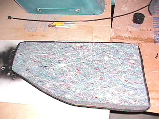
Pic 20 (3/21/00) shows extra batting that I put in, not included in the kit. The other side of the car looks the same but I won't waste the space to post that picture. Most of the white Oklahoma shaped piece of batting ended up being taken back out. There's a curve there where the rubber stopper for the back seat resides and the batting was not about to hold together if I'd have glued it. Not a major problem but it took a while to scrape it out.
Pic 21 (3/22/00) shows the first piece of headliner material installed. The spray can is 3M's Super Trim Adhesive, used for all my gluing (glueing... spell checker says gluing but it doesn't look right!). The binder clips are an idea I gleaned from John Henry's chronology of his headliner installation. They are an absolute must and work like a dream. I bought two dozen, but buy more than that. A lot more.
Pic 22 (3/23/00) OOPS!!! Mistake number one on the headliner. What you're looking at is the space where the back window headliner vinyl meets the side vinyl. And I was being so careful! Not careful enough in this case. We would later cover over it with the piece that goes directly UNDER the rear window but at first we hadn't figured on going that wide.
Pic 23 (3/23/00) is a peek at how I made my seams. I sprayed adhesive on the vinyl then folded it over, giving it a "sewn" look. Then I masked off the area to be glued and sprayed the seam. When the pieces were joined, we got a real nice seam (mostly!).
Pic 24 (3/25/00) shows the installed headliner kit (except the roof which isn't quite done yet in this picture). The windlace is installed as are the panels. I have also installed the insulation and carpeting over the wheel wells, and the luggage compartment carpeting is also installed. You can see the white rubber stopper for the back seat, and up behind the quarter window is part of the latch for my pop out windows. Here's a close up of the latch, but the picture isn't great. Before I installed the vinyl, I cut away the insulation in a nice wide area where the latch would go. Then when the vinyl was put on, I screwed the latch right on top of the vinyl which pulled it nice and tight, but still allowed the latch to be secured right to the metal, with only vinyl and no insulation underneath it.
Pic 25 (3/25/00) is just a shot of my wiring harness. The replacement harness is there, waiting for my modification for the alternator with an internal regulator. Also, the plastic loom visible here with a bunch of wires is my own wiring harness. It runs over the wheel well with the factory one. I cut another hole in the rubber grommet for my wires. These wires are for my gauges and my carb preheater setup (this link describes the setup, pics will be added later).
Pic 26 (3/25/00) Thought I'd better get a picture of the body shop where this is all taking place. I've got a section on my Special Thanks page for Don Schumaker, the owner.
Pic 27 (3/25/00) I painted the gas tank myself. Mixed the sealer coat and the paint coat and sprayed it myself in the paint booth. I guess Don thought I couldn't screw up a gas tank! It turned out real nice, although you can't see much in this picture.
Pic 28 (3/25/00) shows the pop out windows that will be installed onto my car. They're dirty right now but when we get ready to install them I'll clean them up and put in the new rubber I have for them. An older bug nut in town sold them to me for $25 each. Very good condition, straight from a '67 he'd once had. I tried not to say "I'll take 'em" too fast, but as you know they're very expensive to try and buy out of a catalog, especially original ones. I got a great deal on them but I've had them for several years waiting for this day.
Pic 29 (3/25/00) Shows the back seat rail installed along with the front seat belts. The seat belts are all going to come from my donor '74 standard, including these that you see in this picture. Visible under the body you can see what is actually the right rear tire of my chassis. You can also see the sawhorse legs. I'm not going to install the seat until the body is back on the chassis mainly for weight reasons. I had to drill a hole just above the main bolt below the seat belt retractor. There's a stud on the retractor apparently to hold the retractor vertical which was not present on my '67 originally. It's because the retractors lock if they're jerked or tipped, so that stud holds them vertical all the time.
Pic 30 (3/25/00) Here's a picture of my glove box. I don't know if that's the right position for the tire inflation sticker or not but it seemed the most logical to me. I don't think my '67 had a sticker on the glove box originally because it did have one on the gas tank for bias tires, but not one on the glove box door. I saved the one from the gas tank. The actual color of the glove box interior is gray, not readily evident in this picture.
Here are pics posted 4/14/00:
Pic 31 (3/31/00) Here's a look at the completed driver's door. Pretty self explanatory I guess. The glass and vent window is original. New rubber and glass channels.
Pic 32 (3/31/00) shows detail on how I'm running my speaker wires into the doors. The wire is attached to the back side of the plunger stopper and covered with shrink tape. When the door closes, the wire will remain almost stationary, following the plunger back into the door. The other end will run up under the rubber around the keeper pin area. The crap inside there is just old grease, I didn't clean it up as well as I probably should have.
Pic 33 (4/1/00) This is a picture of the passenger door nearing completion. I didn't think about getting a picture of the doors at this stage until I was almost done with this door. You can see the plastic I stretched over the door for draft and sound deadening. It's held in place with double sided rubber tape. You can see the speaker wire hanging out its hole. The black grommets that hold the door panel on are in place.
Pic 34 (4/7/00) OK Der Bugmeister, here it is! The famous Messerschmidt dash. I decided to replace the original speedometer with a VDO replacement so it would look like my other gauges. Also, part of the dash was visible in the recess just in front of the old speedometer which didn't look very nice. Here's the problem: VDO doesn't make a speedo to replace the original. It's much too small, the same size as my tach. I didn't know this until I received it and made some calls to The Real Source and VDO. So we went to work in our minds. Don (the body man) had a chunk of aluminum that looked like the dash so we cut it out to fit as perfectly as possible. Then we found black screws with a hex (allen) head. I carefully drilled and tapped the aluminum dash and attached the new piece to the dash, then screwed the VDO speedometer into it. Although this picture makes it look a little different, it really does look the same as the rest of the dash and looks as if it belongs there. The only thing this picture doesn't show is the idiot lights that I've since added. That's a can of my Java Green acrylic enamel that it's leaning against. Here's a shot of the back side, showing my wiring.
Pic 35 (4/7/00) is just a shot of the carpeting laid out in the car. None of it is glued yet.
Pic 36 (4/14/00) I'm really proud of this deal. If you've ever ordered a new gas tank, you know that the cap attaches differently. This idea came from Don again (a damn valuable asset, I might add). We pried up the tabs on my old gas cap and carefully removed the innards (shown on the left). Then we shot in a bunch of urethane sealer (the windshield stuff) and stuck the new gas cap right down inside the shell of the old one. Carefully wiping away the excess, the result is a perfect combination of the two caps. You can't tell it unless you look directly at the bottom side of the cap, just along the very edges. The new cap has corrugations around it so the urethane grabs it really tight. Of course no gas will ever be near the urethane as the rubber gasket seals the top of the filler neck. This picture shows the other side of the finished conversion.
Pic 37 (4/14/00) Shows another shot of the wiring in the trunk. Close inspection shows the new turn signal relay setup I got from BFY. The jury is still out but it works... the old one did too but I'd been having some trouble with it so I went with a new setup. The black convoluted tubing on the left is my incoming signal wires for the gauges, as well as the wires to control my heat booster fans. Clear up on the right (looking at the picture), that rolled up stuff by the hinge, is the signal wire for the new speedometer. It has a converter to convert from the mechanical cable to electronic which can hook up to the new VDO speedometer. Look carefully at the trunk rubber gasket on the driver's side. I'm an idiot because all I needed to do was thread the gasket under the tin clip. I pried it open before I realized what I was doing. When I tapped it back closed I chipped the paint. Touch up time!
Posted 4/15/2000: I started the car on Saturday, April 15, 2000, almost a full year after I began the restoration. I disconnected the incoming gas line at the fuel pump and held it in a coffee can. Then we gently blew air into the tank until fresh gas came out. After reconnecting that line, I disconnected the line at the carb and held it into the can and had Don crank the engine to get gas thru the filter. After connecting the line again, I set the preliminary timing by the notch on the distributor rim and it fired right up. Ran and sounded very good! Before I started the resto, I removed the gas tank and ran the car until it died so the gas would all drain from everything. I think I need to adjust the idle, but I didn't let it run long enough as we were inside the building.
Pic 38 (4/15/00) Here's a picture looking down into where the gas tank will soon be. The white border is double sided rubber tape I'm putting here for dust control mainly. I haven't peeled off the white paper yet. Looking down near the master cylinder you can see white residue. That's floor dry. I had a mishap with some brake fluid... Compare this to the picture I took of the same area before I started fixing.
Pic 39 (4/15/00) is a shot of my aluminum dash installed. The carpeting isn't done yet as you can see. Compare it to this picture from before. I noticed my tach is reading 1200 rpm or so in this older picture. I must have just started the car and backed it out and left it running. Not important, just something I noticed. My indicator lights are barely visible, but located directly above the speedometer (12 o'clock) is the high beam indicator, and to either side of it is the turn signals. I went with LED lights for these three and wired the LED lights into the turn signal circuits and high beam terminal so that I now have a left and right independent indicator, rather than just the one in the stock speedometer. I ordered two sizes of indicator lights, the small LED's and larger lamp style. The LED's are pretty bright but not blinding so I went with them for the lights that will be on while driving (hi-beam, turn signals). I went with the larger, obnoxiously bright ones for oil pressure and alternator so I'd really notice if they came on. Not visible very good at all in this picture are my idiot lights for oil pressure and alternator. They are bigger indicator lamps and are located to the right of the tach and left of the speedometer. I ordered all the indicator lamps and LED's from Jeg's. This link will take you to my Links and Reviews page. From there you can click to the Jeg's website.
The aftermarket switches on the dash left to right: dome light (I'm lazy), stereo (long story), heater fan control knob, and my on-off-on toggle for my carburetor preheater solenoid. The dome light switch is simple, the ground wire passes along the dash to go to the other door. I simply tapped into it and then grounded the other side of the switch. Yes, I could reach behind me and flick it on, but heck, it's my car and I don't feel like it! The radio switch (can be used for something else if I change radios) is used because my Alpine CD player has no "off" switch. You have to hold the "mute" button for three seconds to turn it off. Who the Einstein was that figured that out I'd like to know... so I put a toggle switch in there. I don't know about the toggle switches. I find them useful and they really don't look too out of place on that steel dash so I went ahead and kept them. Since I'll never sell the car, I allowed myself certain "customizations" that you wouldn't do in a bone stock restoration. Didn't I?? ;) The heater fans are three speed and controlled by the black knob. I'll have a section on my preheater solenoid when I get it done. The wires are ran but I haven't got the solenoid located just yet.
Pic 40 (4/15/00) I completed the carpet installation on 4/15. I apologize for the washed out look of the pictures. It really does look pretty nice in there. Here's another view.
Pic 41 (4/15/00) is a peek at how I did my carpeting. I glued only the tunnel section and the vertical sections up front. The floor pieces aren't glued down. I glued the insulation to the carpet pieces instead so I can remove them for cleaning.
Pic 42 (4/15/00) shows the gas tank installed. The thing we did to the gas cap worked out very well.
Pic 43 (4/15/00) I don't know about this. I wanted to do it, I went ahead and did it, but now I don't know. It'll be fine I guess, I'm the only one who will ever see it anyway. The goal is sound deadening and insulation obviously. My trunk is pretty air tight now and I thought it might help in both very hot and very cold weather, as well as the tin can effect when it's raining hard. Off to the left is a '68 Cutlass we're repairing from a rollover it experienced.
Pic 44 (4/15/00) shows the nearly completed inside of the trunk. Boy those replacement wiring covers are pieces of crap! I ran pinch molding across the top of it so it wouldn't rattle when tucked into place, but still; flimsy as heck. I can't stress enough the negative effect my flash or something has on most of my pictures. The green paint isn't washed out at all, but is really a rich dark green (L518 Java Green). I'm not into photography whatsoever so I don't know what to change. You get the idea, though. When I get it all done I'll take pictures of it outside.
Pic 45 (4/15/00) I probably shouldn't have posted this picture. I sat the back seat back in just to make notes on how I was going to attach the rear parcel shelf. I've got tools and stuff sitting in there. You can see my heat booster fans in place. Only one side of the seat is fastened so that's why it tips a little! You can see plastic hanging in the back and side windows. I use this to cover the bug each night because the glass isn't in yet.
Here's the latest pics I have: Posted 4/20/00 Here are some pictures of my interior. Again, I'm not a photographer so the quality isn't real great. The upholstery is actually TMI's gray, not white like it looks in some of these pictures!
Pic 46 (no date) Here's a picture of my rear seat back. I fastened hinges to it to support the parcel shelf. Also visible here is the new horsehair padding I installed. The TMI upholstery kit fit very well except for the piece for the rear seat back. It fit OK but they really didn't have a way to secure it. I used some screws to fasten it to the back of the frame. Here's a shot of the seat bottom, which turned out very well. I did all the upholstery work myself too. I sandblasted the frames and repainted them flat black, then put new horsehair padding and TMI upholstery on them. I covered areas with burlap in which the springs or wires were rubbing on the upholstery.
Pic 47 (4/19/00) Rocket, Don's dog who is always present in the shop. She mostly sleeps. I was ready to snap a picture of her sleeping earlier when she suddenly got up. It wasn't long before I could take this one, though. She's got a pretty rough life, she and I eat a Twinkie and have milk every afternoon (neither of us need it!) and she drinks beer like one of the guys (loves it, actually).
Pic 48 (no date) The rear seat is out of a '74 Beetle. This is a closeup of the catch that holds the seat back in place, along with a modification I had to do to accommodate it.
Pic 49 (links follow) (4/17/00) Here are three views of the newly installed rear seat. View 1 from the driver's door, view 2 from the passenger door, and view 3 from the front. Astute viewers will notice the seat belts are not original. They are out of my '74 donor Beetle.
Pic 50 (4/19/00) shows the installed front seats. Those same viewers will realize these seats are not original either. They are from a '64, but they were in the car when I bought it. I added an extra spring for lumbar support in the driver's seat when I was working on the frames. The one that was there was broken so I made another and clipped it in place, and fixed the other one. I haven't driven anywhere yet, of course, but the seats seem very comfortable. They seem to offer good support.
On May 13,2000, I'm calling my restoration project "complete" even though it will probably never be totally complete. Here are a few pictures of my car. I'm going to post more when I take pictures on a cloudy day. The sun was too bright in these pictures. Pic 1 (5/13/00) taken from the right front. Pic 2 (5/13/00) taken from the right rear. The dirty white/maroon pickup at the top of the picture is my 1988 Chevy farm pickup. Pic 3 (5/13/00) rear view. Pic 4 (5/13/00) left rear. Pic 5 (5/13/00) front left. Pic 6 (5/13/00) front view. Sort of, the camera must have been shaky. Pic 7 (5/14/00) A view from the left front again, this time at my place. I posted this picture because clear in the upper left background inside the shed you can see the yellow '74 Beetle which has donated many parts, including the engine and back seat. Pic 8 (5/14/00) Here's a good view of the inlet-grafting we did to the decklid. As you know, later model cars had a shorter decklid so we grafted out the inlets and welded them into a used '67 decklid. Turned out very well. Pic 9 (5/14/00) is a look at my backup lights. These were taken from another '67 as mine didn't have these on when I bought it years ago.
|