|
Page added 28th February
2001
 Trestle over Houlaghans Ck, looking towards Junee
18th January 2001
Photo 17bw
|
ARCHIVAL RECORDING
No 1
WHITTON
type TRESTLE
over
HOULAGHANS CREEK
at
492.762km
JUNEE - NARRANDERA
Recording prepared by:
James McInerney
Email: bullack@cia.com.au
|
OUTLINE HISTORY
This Whitton(1)
type underbridge(2)
was constructed over Houlaghans Creek for the opening of the section Junee
to Narrandera on 28th February 1881.
Originally consisting of 7 26ft(3)
spans with horizontally and diagonally braced piers whose round piles
were driven directly into the ground, heavier traffic and ongoing maintenance
has resulted in extra piers without diagonal bracing reducing the spans
to approx 13ft and most of the piers resting on concrete footings.
Piecemeal replacement of the piles has also resulted in many of the round
(tree trunk) piles being replaced with rough dressed 1ft x 1ft square profile
timbers. Extra 12 x 4 1/2 kerb timbers have also been added
to increase the depth of ballast.
It is not known when this augmentation of the piers took place or
when the concrete footings and extra kerb timbers were added.
The underbridge was due to be replaced with a steel and concrete
pier and girder underbridge during February 2001.
CULTURAL SIGNIFICANCE
This underbridge is included in, but not specifically identified
amongst the group entry, No 551 Ballast-Top Timber Openings (Group Entry)
on the draft RAC S 170 Register (4)
. This underbridge is not on either the State Heritage Inventory,
or the State Heritage Register. Likewise, it is not on the (old)
State Rail Authority S 170 Heritage and Conservation Register(5)
. Neither is it listed by the Junee Council.
The underbridge is not mentioned in the history of NSW railway bridges,
Bridges Down Under(6)
, nor is it mentioned in the history(7)
of the Junee to Hay line published in the ARHS Bulletin(8)
in 1982.
ARCHIVAL DOCUMENTS
A search of the Rail Services Australia Plan Room and State Rail
Authority Archives failed to locate any plans(9)
of the underbridge.
RECORDING APPROACH
The recommended guidelines(10)
were followed whilst preparing the Archival Recording of this underbridge.
| i. A photographic record(11)
of the underbridge was compiled on Thursday 18th January 2001. |
ii. Drawings of the bridge were prepared using the above
photos and measurements and field notes
made during the abovementioned site
visit. |
iii. Completed copies of this recording will be located in
readily accessible locations, eg ARHS Archives,
the Internet and the NSW Heritage
Office. |
1. John Whitton
was the Engineer-in-Chief of the NSW Railways from 1857 till 1890 and was
responsible for the adoption of this style of
timber trestle on the system. This type of trestle has become known
as the Whitton type to distinguish it from later styles.
2. In
railway terms an underbridge is a bridge that carries a railway line
over something.
3. 26ft was
the standard span for trestles when this one was constructed, P26 Bridges
Down Under Don Fraser 1995 ARHS NSW.
4. RAC. 1999.
Heritage Management Policy Manual (Draft). RAC
5. SRA. 1993.
Heritage and Conservation Register Summary. SRA.
6. Bridges
Down Under Don Fraser 1995 ARHS NSW.
7. The Centenary
of the Railway from Junee to Hay N J Pollard ARHS Bulletin April,
May, June, July 1982
8. The
ARHS Bulletin is a magazine devoted to the history of Australian railways
and is published monthly by the
Australian Railway Historical Society
9. Standard
practice of the time this bridge was built was for a master plan for
this type of bridge to be prepared and the basic design
adapted locally to suit a particular site. Individual plans of each
structure were not normally prepared.
10. How to Prepare
Archival Records of Heritage Items NSW Heritage 1998.
11. As per Guidelines
for Photographic Recording of Heritage Sites, Buildings, Structures and
Moveable Items NSW Heritage 1998.
LOCATION PLAN

PHOTOGRAPHIC BASE PLAN
PHOTOGRAPHS
THE TRESTLE IN THE LANDSCAPE
Click on the photo number to see the full-size
photograph.
 |
Photo
1w |
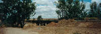
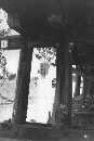
Approaching from the west along the access road, the first view
of the trestle shows it through a gap in the trees that line Houlaghans
Creek. |
|
|
|
 |
Photo
2w |
Climbing onto the formation and looking south we see the reason
for this trestle's existence, Houlaghans Creek. As is typical of
Australian climatic conditions, (especially in summer), the creek is dry,
but when the rains come, the volume of water that can suddenly appear is
more than enough justification for the substantial timber trestle, (and
its concrete and steel replacement). |
|
|
|
 |
Photo
3w |
Turning around and looking north we see another view of Houlaghans
creek. It passes under the railway just out of picture to the right. |
|
|
|
 |
Photo
1A |
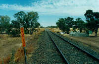
Little is visible of the bridge in this view looking west towards
Old Junee, though the trees in the middle distance mark the course of Houlaghans
Creek in a landscape that consists mainly of cleared paddocks. The
20km caution marker is a good indication of the operational reasons that
have made replacement of life expired timber bridges necessary for the
modern railway. Sections of the replacement steel and concrete bridge
are stored to the right. |
|
|
|
 |
Photo
2A |
Another distant view of the bridge showing the low impact on the
visual environment of timber trestles. The grey upright structures
are the concrete piers of the new bridge. |
THE TRESTLE
 |
Photo
21 |
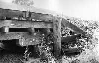
The southern side of the trestle, looking east. The purpose
of the cross timbers jutting out from the lower kerb is not known, and
they do not appear on the northern side of the bridge. |
| |
|
|
 |
Photo
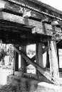
22 |
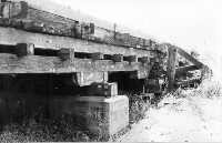
The eastern end of the north side of the trestle, with the piers
for the new bridge prominent. |
| |
|
|
 |
Photo
23A |
A closer view, looking southwest. The concrete piers for the
new structure stand out in the mid distance. |
| |
|
|
 |
Photo
24 |
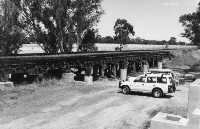
The previously mentioned sections of the new bridge provide a convenient
vantage point to view most of the northern side of the trestle. |
DETAIL VIEWS
 |
Photo
20bw |
The western abutment and span no 13, looking north. |
| |
|
|
 |
Photo
19A |
The southwest abutment wingwall showing the km marking (from Sydney
Terminal), which normally appears on the left hand Down end wingwall of
all NSWR bridges. Traditionally, the identification number of the
Gang responsible for the maintainance of the bridge also appeared here,
but with the changes that have occurred in maintainance procedures in recent
years this practice appears to have ceased. |
| |
|
|
 |
Photo
18A |
A close up of the construction details of the spans looking east
towards Pier 13. |
| |
|
|
 |
Photo
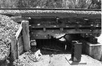
18bw |
A veiw of Piers 13 and 12 from the south side of the bridge.
When the creek is flowing it flows throught his area. |
| |
|
|
 |
Photo
16bw |
The western abutment from the other side, note that the cross pieces
that intersect the lower kerb pieces in photo 20bw don't appear on this
side of the bridge. It would appear that the abutment pier has partially
collapsed. |
| |
|
|
 |
Photo
15bw |
Pier 13 has the highest visible concrete footing. |
| |
|
|
 |
Photo
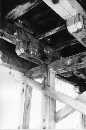
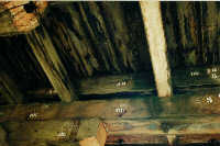
14bw |
Looking up under the span at Pier 10 we can see details of the construction. |
| |
|
|
 |
Photo
13bw |
Looking south at Piers 7, 8 and 9. The major visual difference
between the "Whitton" style trestles and the later "Deane" style is prominent
here; the depth of the span structure. The "Deane" style were much
less substantial in this area, which caused much adverse comment regarding
their safety from those more comfortable with traditional English construction
when the American style "Dean" trestles replaced the "Whitton" trestles
for new construction in the 1890s. |
| |
|
|
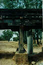 |
Photo13A |
A closer view of Pier 8 and the massive construction of the spans.
The piles were originally approx 1ft (600mm) diameter tree trunks, but
some have been replaced with 1ft x 1ft rough dressed square section timber,
as can be seen here |
| |
|
|
 |
Photo
12bw |
A view of Pier 1 showing the construction, a simple headstock of
timber on a concrete pier. No 1 is one of the piers added later to
strengthen the original 26ft spans, dividing them into two 13ft spans. |
| |
|
|
 |
Photo
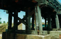
12A |
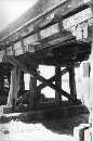
Pier 2, one of the originals, showing how it has been strengthened
by the addition of T shaped timber supports resting directly on the ground.
The purpose of the stenciled numbers is not known, but may be connected
with the impending demolition of the bridge. |
| |
|
|
 |
Photo
11bw |
The eastern abutment and southern wingwall. The horizontal
timbers have disintegrated, allowing ballast to cascade down the slope.
As the bridge is about to be demolished it was obviously regarded as being
a waste of time and money to repair the wingwall. The abutment piers
at this end have disappeared and have been replaced with a variety of timber
packing. |
| |
|
|
 |
Photo
10bw |
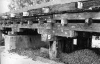
Piers 2and 3, showing construction of the spans and the shorter
piers at the eastern end of the bridge. |
| |
|
|
 |
Photo
10A |
Pier 3, another of the simple timber on concrete intermediate piers.
The subtle colours of the weathered timber and the concrete are worth noting
for those who will use this information for the building of models. |
| |
|
|
 |
Photo
9bw |
The piers are all numbered in black stencil on a white background,
starting from No 1 at the Sydney end. |
| |
|
|
 |
Photo
9A |
Pier 5, showing construction details of the intermediate piers.
As mentioned previously, The intermediate piers do not have diagonal bracing. |
| |
|
|
 |
Photo
8bw |
Photo 8bw (left) and 8A (next below), showing construction details
and the extra span timber that has been added between the outermost spans
on the right between Piers 6 and 8. |
| |
|
|
 |
Photo
8A |
|
| |
|
|
 |
Photo
7bw |
Pier 4, one of the original piers, showing the substantial diagonal
bracing carried on the original piers. Also visible are details of
the span construction. Cross reference with the drawings will
show that piers 4 and 5 are approximately 2ft (600mm) shorter than
piers 6 to 12. |
| |
|
|
 |
Photo
7A |
Looking up under the deck near Pier 9 at the details of the massive
construction of the spans. |
| |
|
|
 |
Photo
6bw |
A close up of Pier 10 showing construction of the original piers,
with their diagonal bracing, and of the spans, showing some of the transverse
transoms. |
| |
|
|
 |
Photo
6A |
Closeup of the footings to Pier 10. |
| |
|
|
 |
Photo
5bw |
A view showing the underside of the span structure in the vicinity
of Pier 9 |
| |
|
|
 |
Photo
5A |
Looking west from Pier 9, which is one of the intermediate piers
without diagonal bracing. Evidence of scouring around the bottom
of the concrete pier foundations is visible. A variety of steel bolts
and plates serve to secure the various parts of the bridge. The circular
concrete and steel girder structure to the right is one of the piers for
the new bridge under construction. |
| |
|
|
 |
Photo
4A |
Piers 10 and 11, allowing comparison between the original piers
with their diagonal bracing, (Pier 10) and the intermediate piers (Pier
11) that were added sometime after original construction and do not have
diagonal bracing. The mixture of round and square section piles mentioned
above can also be seen. |
| |
|
|
 |
Photo
3A |
Piers 12 and 13 at the western end of the bridge. |
MEASURED DRAWING
Click
here to view the complete drawing
The drawing of the trestle is drawn to a ratio of 1:87. This
is the ratio of the most commonly used railway modelling scale in Australia
(and the world), which is known as HO. It is drawn to this scale
as the most likely mass users of this information are likely to be railway
modellers.
The drawing is dimensioned in Imperial measurements (Feet and Inches),
rather than today's metrics as the structure was constructed in the Imperial
(measurement) era and many of the major dimensions do not make
sense when directly converted to Metric. Also, as the abovementioned
model railway scale, (HO) is commonly measured as 3.5mm to the foot(1),
having it in Imperial also makes it more useful for most of the potential
endusers.
1. This strange mixture
of Imperial and Metric is used for reasons connected with the early days
of the hobby in Great Britain and cannot
be explained in a short footnote!
The information
above is provided for the use and information of fellow modellers and enthusiasts
and may
be reproduced for private use. For permission for Commercial reproduction
and use on
other web
sites please contact the Copyright holder:
James
McInerney
|