
SeGuruCool
The Largest Independant Solid Edge Resource Outside UGS

SeGuruCool The Largest Independant Solid Edge Resource Outside UGS |
|
Part 1 of 3 www.oocities.org/SeGuruCool  segurucool @ indiatimes.com segurucool @ indiatimes.com |
|
|
|
In this tutorial you learn : It is assumed that you are familiar with the basics of Solid Edge Part modeling. |  |
|
Drawing the profile - Front view Start with creating a sketch in the the y-z plane. Using the Curve  tool, create the outline of the top part of the bonnet. tool, create the outline of the top part of the bonnet. See figure. |  |
|
More profiles Create another curve in a plane parallel to the y-z plane. Constraint the lower end-points of the curves to be horizontal. |  |
|
Once More Create another curve in a plane parallel to the y-z plane. See figure. Take care that the bottom end-points of all three curves lie in the same plane. | 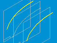 |
|
Curve in x-y plane Draw a curve in a plane parallel to the x-y plane and passing through the end points of the three curves drawn in last step. See figure. Connect the curve well to the end points of all three curves. | 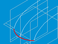 |
|
The BlueSurf - First Curve Click the BlueSurf  tool on the surfacing toolbar. tool on the surfacing toolbar.Select the curve as shown in figure. Click accept  on the ribbon bar. on the ribbon bar.
|  |
|
The BlueSurf - Second Curve Select the curve in the middle and click accept  on the ribbon bar. on the ribbon bar. Both - correct and incorrect - ways of picking the second curve are shown in figure. Pick in the correct way. |  |
|
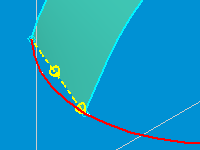
BlueSurf Appears Click accept  and then Preview. and then Preview. A BlueSurf will be created as shown in figure. This bluesurf connects the endpoints along a straight line as indicated with the yellow dashed line. We want to guide the surface along the curve at the bottom. Still in the BlueSurf command, click the Add Guide Curves  button on the ribbon bar. button on the ribbon bar. Select the curve as shown and click accept 
|  |
|
BlueSurf changes Form The blueSurf changes its form as shown in figure. |  |
|
Extend the Bluesurf Next, select the third curve as shown in figure. Click the accept  Preview and Finish buttons in that order. Preview and Finish buttons in that order. |  |
|
BlueSurf Created A BlueSurf, as shown in figure, is finally created . This surface spans the three curves and is guided by the curve at the bottom. |  |
|
Extruded Surface - Create the Curve Create a curve in the x-y plane as shown in figure and mirror it. Connect it well to the endpoint of the bottom curve as shown. | 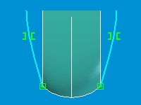 |
|
Extruded Surface - Iso View From an isometric view, the sketch looks like as shown in figure besides. | 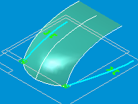 |
|
Extruded Surface - Done Click the Extruded Surface  tool on the surfacing toolbar. tool on the surfacing toolbar.Select the curve as shown in figure. Indicate height in the vertical direction well above the bluesurf. An extruded surface is created as shown in figure. |  |
|
Prepare to Project In a plane parallel to the y-z plane, create a curve as shown in figure. |  |
|
Project Curve - Curve Step Select the Project Curve  tool from the Surfacing toolbar. tool from the Surfacing toolbar. Select the curve created in last step as the curve to project. Click accept  on the ribbon bar. on the ribbon bar.
|  |
|
Project Curve - Body Step Select the extruded surface as the surface to project on. | 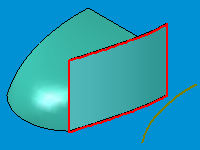 |
|
Project Curve - Direction Step Point the arrow towards the extruded surface and click. Click Finish on the ribbon bar. |  |
|
Click Here to go to part 2 of this tutorial |
Tushar Suradkar  segurucool @ indiatimes.com segurucool @ indiatimes.com |